 |
|||
|
|
|||
|
Special Feature on Technical Solutions to Real-world Problems Vol. 5, No. 7, pp. 8–10, July 2007. https://doi.org/10.53829/ntr200707sf2 Tool for Checking for Optical FiltersAbstractNTT has developed a technique for determining the presence and type of optical filter remotely from a central office. Although the state of an optical fiber line can be tested during service by using an optical pulse tester or other device, it is necessary to have an optical filter installed at the terminal of the optical circuit to prevent optical services being disrupted. This new technique will make it possible to cross-check with a database before a line is tested.
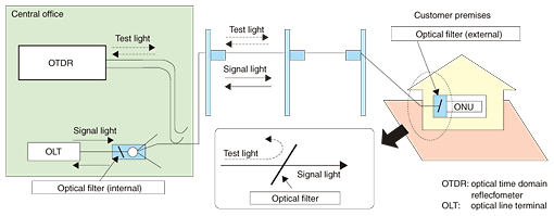
1. What is an optical filter?The number of optical subscriber lines has been increasing rapidly in parallel with the expansion of IP (Internet protocol) broadband optical services centered on NTT's B FLET'S Internet connection service. However, this expansion has been accompanied by an increasing number of optical-circuit faults, so there is a need for more efficient maintenance procedures. NTT has begun using an optical-fiber maintenance support system called AURORA (automatic optical fiber operations support system) with the aim of increasing the efficiency of repair work performed at the time of an optical-fiber-line failure. The system includes an optical pulse testing function for locating a fault. This function can be performed even while services are being provided by using a test light having a wavelength different from that of the signal light. However, it is necessary for an optical filter to be installed immediately in front of the customer's terminal (ONU: optical network unit). This filter passes the signal light while cutting off (reflecting) the test light. Optical-fiber-line testing from an NTT central office using an OTDR is outlined in Fig. 1.
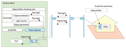
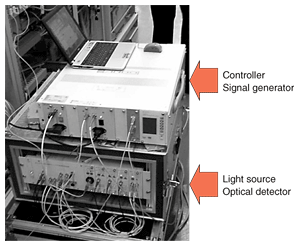
As optical services like B FLET'S continue to expand, a database of optical filters installed at customer terminals is being constructed. However, there are still situations where the presence and type of optical filter is unknown. This prevents the testing of active optical circuits. It is impractical to dispatch someone to check the customer's terminal directly because this involves too much effort in terms of on-site human labor and also requires the customer's consent. Therefore, there is a need for a tool that can remotely check for the presence of an optical filter and determine its type if one is present from a central office without affecting the active circuit. 2. Outline of optical filter checking toolThis tool obtains information about the customer's terminal filter by transmitting test light to the far end of the optical fiber line from the central office and then detecting and analyzing the reflected light. The optical filter checking tool is shown schematically in Fig. 2 and a photograph of the actual equipment is shown in Fig. 3.
The main components of this tool are a light source for transmitting the test light (including a signal generator), an optical detector for detecting and analyzing reflected light, and a controller. The tool's main features are summarized below. (1) The presence of a filter can be checked and its type determined from an NTT central office. (2) The customer's terminal can be checked without disrupting services. (3) Automatic measurements can be performed by existing fiber selectors and optical-cable-testing support tools independent of the AURORA database. (4) Feedback can be provided to Optos (outside plant provisioning and intelligent operating systems) databases. 3. Checking methodSince the optical filter is designed to strongly reflect light in the target band, the presence of a filter and its type can be determined by measuring the intensity of reflected light for test lights of different wavelengths injected into the optical fiber line and using the relationships shown in Table 1. Test lights with three different wavelengths are used: 1.33, 1.53, and 1.65 µm.
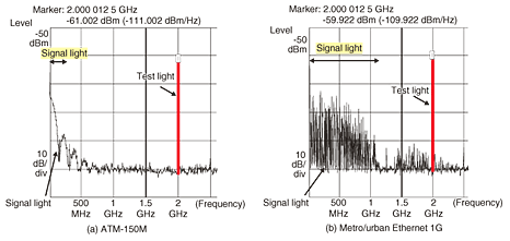
When no filter is installed before the ONU, there is no reflection of test light, so the intensity of reflected light is small for all three wavelengths. If a 1.55 µm filter is present, the intensity of reflected light is large for 1.53 and 1.65 µm test light while that for 1.33 µm test light, which has a shorter wavelength than the blocked band, is small since it passes through the filter. Finally, if a 1.65 µm filter is present, the intensity of reflected light is large for 1.65 µm test light while that for the 1.33 and 1.53 µm test light with wavelengths shorter than the blocked band is small since those wavelengths pass through the filter. By analyzing the relationship between test light wavelength and reflected light intensity in this way, we can determine whether a filter to present and what type it is. 4. Why are active circuits not affected?This tool is used to transmit test light to terminating equipment on a customer's terminal over an active circuit when no information is available about the presence and type of optical filter. However, it is essential to avoid service disruption even if it turns out that no filter is installed. After an examination of the frequency spectrum of optical services, it was decided that the test light should be chosen to have wavelengths that would not affect the signal light even if no filter was installed before the ONU. The theoretical frequency spectra of ATM-150M (ATM: asynchronous transfer mode) and metro/urban Ethernet 1G are compared with the frequency spectrum of 2-GHz test light in Fig. 4. The modulation frequency of the test light was chosen to be 2 GHz on the assumption that the bit rate of optical services is under 1 Gbit/s. The test-light spectrum falls in an area where it will not affect the frequency components of the provided services. To verify this, we conducted a field test to check actual optical filters during the provision of various services (ATM, metro/urban Ethernet, INS-Net 1500, RSBM (remote subscriber module), etc.) on about 10,000 active circuits in western Japan. No disruption to active services was observed.
5. Deployment statusThis tool was first deployed in July 2004 in western Japan. There are plans to expand its use to all NTT branch offices. This tool is effective for constructing a database that raises the efficiency of optical fiber line maintenance. |
|||


