 |
|||
|
|
|||
|
Special Feature on Technical Solutions to Real-world Problems Vol. 5, No. 8, pp. 18–20, Aug. 2007. https://doi.org/10.53829/ntr200708sf5 Heat Management in VDSL Switch InstallationAbstractSince a VDSL switch must be operated in a suitable temperature environment, heat countermeasures are provided to cope with various installation environments. The NTT East Technical Assistance and Support Center has verified heat countermeasures for a VDSL switch mounted on a 19-inch rack. This article introduces them and overviews various other heat countermeasures.
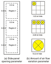
1. Optical broadband service and VDSLVDSL (very high-bit-rate digital subscriber line) is becoming widespread as a way to provide broadband service to apartment buildings. The VDSL switch uses optical fiber up to the entrance of an apartment building and then connects to each residence in the building via telephone lines. The VDSL switch, line terminating equipment, and VDSL equipment for distribution to each residence are installed in a common area in the apartment building. The VDSL switch in particular is installed in environments having a wide range of temperatures. For stable operation and good quality of service (QoS) to the customers even under such conditions, a rack and cabinet selection method and various installation methods are available. 2. Location for installing VDSL switchThere are various methods of installing the VDSL switch according to the size, construction, and facilities of the apartment building. For large apartment buildings that have an MDF (main distributing frame) room, the VDSL switch is mounted in a 19-inch rack and installed in that MDF room. If there is no spare space in the MDF room or if the building is small and does not have an MDF room, a wall-mounted installation or other such means is used. In that case, a cabinet is hung on a wall and the VDSL switch is mounted in the cabinet. The installation location is generally the apartment building lobby, an elevator shaft, an open corridor, or a common area. In addition to the temperature conditions, the choice of rack or cabinet and installation method requires an overall evaluation of security, electromagnetic noise, noise, dust, exposure to wind and rain, and other such factors. This article presents results concerning temperature conditions assuming installation in a 19-inch rack in an apartment building that has an MDF room. 3. Experimental verification of temperature conditions for 19-inch rack mountingIf only the temperature conditions are taken into account, forced-air cooling and an open-rack mounting system can be considered. In an actual installation environment, however, the problem of dust and the need for security may prevent the use of an open rack. Forced-air cooling also creates noise problems, so it is necessary to control the volume of air flow. A thermostatic chamber, which can model changes in the open-air temperature, was used to verify the assumed relationship between the open-air temperature and the power consumption of equipment in a rack-mounted installation, with the size and shape of air vents, the air-flow volume, and other such values treated as parameters. The parameters related to the openings and amount of air flow used in the experiments are shown in Fig. 1. The openings divide the side panels into three regions, as shown in Fig. 1(a). The area of the punched metal openings was used as the parameter. The amount of air flow was controlled by the size and number of fans, as shown in Fig. 1(b).
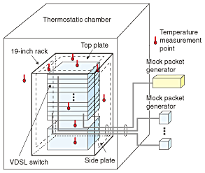
An overview of the measurements taken in the experiments is presented in Fig. 2. Various numbers of VDSL switches mounted on a 19-inch rack were placed in a thermostatic bath that is sufficiently larger than the 19-inch rack. A mock-packet generator was connected to apply an appropriate load to the VDSL switch and allow QoS measurements. The temperature was measured at nine points inside and outside the rack to obtain the temperature distribution.
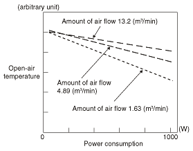
4. Assumed relationship between open-air temperature and power consumptionAnalyzing and evaluating the measured values from the experiments described above can reveal, for example, the limiting temperature that satisfies a given QoS and the power consumption of the mounted VDSL switch. The analysis results are presented in Fig. 3. The greater the amount of air flow, the higher the permissible open-air temperature. Therefore, if a low open-air temperature is assumed, a rack with less air flow and thus less noise can be selected. Such verification and analysis results can be referred to as a basis for selecting rack or cabinet mounting in on-site work manuals and examples.
5. Important points concerning heat countermeasuresAs explained above, the choice of rack or cabinet is important, but the installation method parameter is just as important. The important points concerning the installation method are explained below. 5.1 Heat countermeasures for 19-inch rack installationsAdequate ventilation space must be maintained between the 19-inch rack and walls or other obstacles. Furthermore, if an air intake is placed on the same surface as a heat exhaust, then a short circuit may occur in the air flow and the internal rack temperature will rise. In a dense installation of multiple 19-inch racks, it is important that the installation allows for a cool air flow and a warm air flow. 5.2 Heat countermeasures for cabinet installationsFor cabinet installations in open corridors or semi-outdoor locations, it is important to prevent exposure to direct sunlight. It is also important that installation fittings do not block the vents. 5.3 Installation room temperatureIf, after installation of the VDSL switch, the size of the MDF room or other installation room is not adequate for the VDSL switch and other heat-generating equipment that are installed, it is necessary to investigate the ventilation and temperature control systems of the equipment installation room. 6. Future developmentThis article introduced heat management techniques for various installation environments of the VDSL switch. In the future, the problem of heat is likely to increase steadily as more powerful CPU (central processing unit) chips and more advanced specifications are used in the various types of communication equipment. Therefore, the same kinds of heat countermeasures as are used for the VDSL switch will become necessary for the equipment used in various other network services as the performance of that equipment advances. NTT East will proceed with continuous investigation and verification of various kinds to prevent heat-related problems in products developed in the future in order to continue to provide stable services. |
|||


