|
|||||||||||||||||||
|
|
|||||||||||||||||||
       |
Special Feature: EMC Technology for IP Network Infrastructure Vol. 5, No. 12, pp. 52–56, Dec. 2007. https://doi.org/10.53829/ntr200712sf3 EMC Countermeasure Technology for Best-effort Broadband Communication ServiceAbstractThis article describes EMC (electromagnetic compatibility) countermeasure technology for best-effort broadband communication services. Among such services, IP-VPN (Internet protocol virtual private network) and wide-area Ethernet play important roles as corporate local-area networks, as substitutes for leased lines. Moreover, the number of subscribers to VDSL (very-high-bitrate digital subscriber line) services in multi-dwelling housing units, such as apartments and dormitories, has been increasing rapidly because VDSL can easily be connected to long-span optical lines (fiber to the building). 
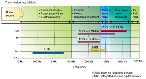
1. Changes in the electromagnetic environment for best-effort communication services1.1 Popularity of best-effort communication servicesSince 1996, with the advent of the OCN (open computer network) service in Japan, the term “best-effort communication service” has been used to describe a communication service that shares the transmission bandwidth among multiple users and makes the best use of network resources. It aimed to provide a broadband service at a low price from the very beginning rather than guaranteeing a minimum level of transmission quality. As a result, broadband communication services have been offered in Japan for over ten years at prices that are very competitive with prices in other countries. IP-VPN (Internet protocol virtual private network) and wide-area Ethernet are typical best-effort communication services: the number of subscribers to these services, as a substitute for the leased lines, is growing by leaps and bounds. Similarly, the number of broadband access (e.g., B FLET'S service) subscriptions for multi-dwelling housing units, such as apartments and dormitories, has increased rapidly as a result of the appearance of VDSL (very-high-bitrate digital subscriber line). This uses optical fiber to the building and then VDSL over existing premises wiring to reach individual subscribers inside the building [1]. 1.2 Use of power saving functions in communication equipmentAs best-effort communication services have become the mainstream for those services instead of bandwidth-guaranteed services, power-saving technology has been introduced in various types of communication equipment (e.g., routers and media converters). Although the electronic circuits in communication equipment can be operated with small-amplitude signals, they are affected by even a slight amount of electromagnetic noise. Inverter technology, which improves the efficiency of electrical power supplies, has also progressed and been applied to communication equipment. Inverters generate wideband noise from 100 Hz to 100 kHz when they are converting a DC power supply to an AC power supply, and noise problems have been reported. However, an immunity testing method [2] for electromagnetic disturbances below 150 kHz, like inverter noise, is not prescribed in the present standardization agreements, so discussions about one are being held in some standards-setting organizations (e.g., ITU-T SG5). 1.3 Wider transmission bandwidthThe relationships between the transmission bands of communication services and electromagnetic disturbance sources are shown in Fig. 1. The main electromagnetic noise mixed in the transmission band of a telephone subscriber line is induction noise from electric power generation or electric railway equipment; this is called audible noise. Its influence can be prevented by moving the wiring underground or changing the route of the lines. Even when electromagnetic noise from broadcast waves or ham radio invades the communication line, the noise component outside the transmission band can be decreased by inserting a common-mode filter into the line.
On the other hand, it has been difficult to control the noise component in the DSL transmission band because the electromagnetic noise from broadcast waves or ham radio overlaps the service transmission signal. Three kinds of noise filter are available. Since they have different noise suppression bands, we must choose the filter with the optimum noise suppression characteristics for the frequency of the noise [3]. Moreover, we must consider that even when the optimum filter is inserted into the line, the transmission rate could be degraded. 1.4 Expansion of installation locationsThe places where communication equipment is installed have grown in number and become more diverse along with the progress of best-effort communication services. Most communication equipment is now placed where other types of electrical equipment are connected to the same electric power system, so the electromagnetic environment around communication equipment is becoming worse. For example, the electromagnetic noise from some inverter devices is mixed or induced into communication equipment through power supply lines. In particular, in places where the power supply for room lighting or air conditioners is controlled remotely from a central location, almost all the electrical devices are turned on and off at the same time. This imposes a huge impulsive noise on the power supply system. Communication equipment (e.g., routers) operating when the switch turns on or off is affected by this impulsive noise. Furthermore, most places of this type are unmanned facilities and it is difficult to provide earth connections that are appropriate for this electromagnetic noise. Therefore, there are many cases where communication equipment is operated without an appropriate earth connection even when an earth terminal is available. For communication equipment that has an earth terminal, the immunity tests in IEC 61000-4 series and ITU-T recommendation K series are conducted with the earth ground connected. Thus, the immunity test conditions are increasingly diverging from the actual practical environment of communication equipment. 2. EMC countermeasure technology to support best-effort communication services2.1 Issues of EMC countermeasure technologyThis section describes the various changes in the electromagnetic environment for best-effort communication services. There are many issues involved in EMC countermeasure technology for improving the reliability and convenience of best-effort communication services. For example, the following EMC countermeasure technology is required.
(1) Noise filtering technology for the DSL transmission line, whose normal-mode insertion loss is small and whose common-mode noise suppression efficiency is high.
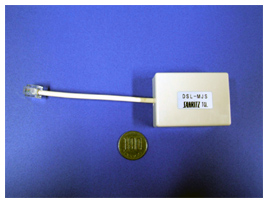
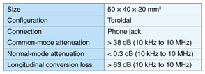
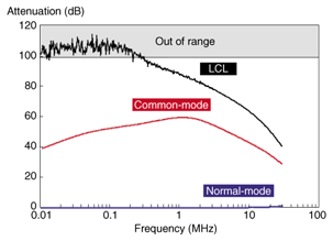
(2) Noise filtering technology applicable to the broadband noise from inverter devices and power supply switches. (3) Noise filtering technology applicable to nonearthed connections. To solve these three issues, a noise filter for lines carrying DSL services and a power supply tap with built-in noise filter are introduced in sections 2.2 and 2.3. 2.2 DSL noise filterA photograph of our noise filter for lines carrying DSL services is shown in Fig. 2. The filter's main specifications are listed in Table 1. Its attenuation characteristics—common-mode loss, normal-mode insertion loss, and longitudinal conversion loss (LCL)—are shown in Fig. 3 [4]. The developed product has a size of 50 × 40 × 20 mm3 and uses a plug-in phone jack type of connection. The filter has a toroidal geometry and the core uses high-permeability material. Therefore, the common-mode attenuation is over 30 dB in the frequency range from 10 kHz to 10 MHz. Inserting a plug-in phone jack type of noise filter into a transmission line generally leads to degradation of the LCL and an increase in transmission loss. Our noise filter provides more effective EMC countermeasures than previous ones because it produces low insertion loss (less than 0.3 dB), high noise attenuation, and high LCL (more than 63 dB) in the transmission band of the DSL signal (10 kHz to 10 MHz). These characteristics are achieved by optimizing the twisting method and the number of twists for the two lines.
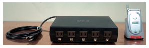
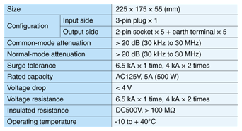
2.3 Power supply tap with built-in noise filterA photograph of a power supply tap with the noise filter described above built into it is shown in Fig. 4. The tap's main specifications are listed in Table 2. The developed product is 225 × 175 × 55 mm3 in size and its rated capacity is 500 VA (5 A, 125 V). It is more efficient as a filter for noise from power supply systems because it is light and small compared with a noise-cut transformer having the same rated capacity. In particular, it is convenient where the available installation space is small, i.e., in a main distribution frame room containing VDSL concentrators.
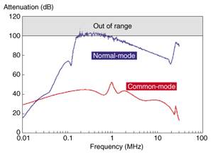
The common-mode and normal-mode attenuation characteristics of this developed product are shown in Fig. 5. Without an earth connection, they are both more than 20 dB in the range from 30 kHz to 30 MHz, which corresponds to impulsive noise, i.e., inverter noise or switching noise.
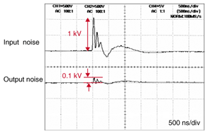
The power input cable has a three-pin plug and the output side has five two-pin sockets, each with an earth terminal. When the earth terminal is connected to ground, this filter achieve better noise attenuation than when there is no earth connection and it also protects against lightning surges. The noise attenuation measured for an impulsive disturbance of 1 kV using the EFT/B (electrical fast transient/burst) immunity test specified in technical requirement (TR549001) is shown in Fig. 6. The amplitude of the impulsive noise became 1/10 of the input noise, which shows that this product has sufficient noise attenuation for broadband impulsive noise.
3. Improved reliability for best-effort communication servicesSome devices have included EMC countermeasures in the design stage since the 1990s. Although EMC design is a kind of risk management to prevent future trouble and is very important, it increases the development costs and the final price of the product. On the other hand, the EMC countermeasure technology described in this paper will be implemented in the introduction phase of products or communication services. Both EMC design and countermeasure technology are necessary to provide low-cost reliable communication services. The NTT Group has set a Technical Requirement (TR) for the immunity of communication equipment. It procures and introduces communication equipment that satisfies this TR. It is also trying to develop the EMC technology required for other communication services and establish a framework for resolving any network trouble quickly as communication services continue to progress. References
|
||||||||||||||||||