|
|||||||||||||||||||
|
|
|||||||||||||||||||
       |
Special Feature: EMC Technology for IP Network Infrastructure Vol. 5, No. 12, pp. 57–61, Dec. 2007. https://doi.org/10.53829/ntr200712sf4 Grounding Technology for the Advancing Communication InfrastructureAbstractThis paper discusses problems related to grounding in a communications center building. The communication environment has changed greatly as communication systems move toward broadband and IP (Internet protocol) technology. Although grounding technology has been studied for a very long time, these changes have led to new grounding problems. 
1. Purposes of communication system groundingThe communication systems that are installed in center buildings currently operate on either an alternating current or direct current power supply. These systems have several grounds to provide the standard electrical potential for proper operation and to protect people and communication devices from dangerous voltages. The types of communication system grounding and their purposes are presented in Table 1 [1]. Communication systems have been changing recently, with the communication environment moving toward broadband communication and IP (Internet protocol) technologies. Although the purposes of these grounding methods have not changed, the conventional grounding configurations have sometimes had difficulty coping. The grounding problems that arise as the communication infrastructure is converted to IP technology are explained in the next section.
2. Grounding problems for communication systems2.1 Grounding problems for large-capacity IP communication systemsLarge-capacity IP communication systems require high processing capabilities, which has resulted in year-by-year increases in electrical power requirements. The change in power consumption of IP routers is shown in Fig. 1. For both edge routers and core routers, newer systems have greater power consumption. In particular, some large-scale routers consume over 10 kW per unit [2].
When short circuits or earth faults occur in such high-power-consumption communication systems, a higher current flows through the power line or the grounding line than in previous systems. In that case, fuses or circuit breakers are needed to cut off the power supply current in order to protect the equipment. If the grounding system is unsuitable, however, the high current cannot be interrupted by fuses or circuit breakers, and there may be problems such as heating or melting of the grounding line or electromagnetic interference with peripheral devices caused by the inductance created by a sudden change in current. 2.2 Connection methods for communication system grounding terminalsThe construction of the IP network infrastructure differs from existing legacy communication systems in that many commercial IP systems are being introduced into center buildings. The notation of those grounding systems and its meaning sometimes differ from the notation used in NTT communication center buildings. The grounding terminal labeling for the communication systems installed in NTT center buildings includes “G” (-48 V positive-side line), “E” (used for the signal ground of electronic devices), and “FG” (protective ground to prevent electrical shock). Commercial communication systems sometimes also use the “E” label, but it sometimes means a protective ground terminal. Such differences from the meaning of the NTT notation invite confusion and could lead to incorrect connection. That situation makes it necessary to confirm that the grounding terminals used in the communication devices of manufacturers and those used by NTT match in terms of purpose and approach. Accordingly, it is necessary to both clarify NTT's approach to grounding and proceed to study how to achieve communication system grounding connections that suit the design purposes. 3. Problems concerning grounding in center buildings3.1 Problems concerning interface BSince there is some resistance between the actual grounding line and the ground, if the grounding connections of the communication system and the power system are long, a difference in electrical potential between the grounds may occur when a center building is struck by lightning. Such a difference in ground potential may create a high voltage between interconnected systems and cause a system or cable failure. To solve this problem of electrical potential difference, the isolated grounding method was introduced in the latter half of the 1980s. The conventional center building grounding method and the isolated grounding method are compared in Fig. 2.
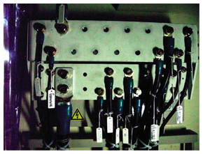
In the isolated grounding method, grounding to the earth is achieved by the center building's single grounding pole, which is referred to as interface A. From there into the building, a large-diameter conductor called the grounding bus is installed perpendicular to the ground. On each floor of the building is installed an interface B, to which all of the equipment on that floor is grounded. Introducing the isolated grounding method clarifies the structural units of the grounding system and is an improvement with respect to measures against lightning damage and maintenance [3]. This grounding method has been made the standard for NTT center building grounding. The number of grounding box terminals specified for an ordinary interface B is eight, and this number can be increased to 23 using terminal strips. The connections in a general interface B are shown in Fig. 3.
At the time those internal standards were being studied, the number of systems installed in center buildings was on that scale, and the grounding terminals in most center buildings were sufficient. However, the number of communication systems increased as a result of the changes in the communication environment, and now multiple switching units are being introduced on the same floor. The grounding lines for those systems and their power supply systems are connected to the interface B. As a result, the number of interface B terminals has become insufficient. A simple work-around is to connect two grounding lines to a single terminal. Such multiple connections to an interface B terminal pose problems when temporary disconnection is necessary for removal or modification of a grounding line because such work affects all of the systems connected to that terminal. Many more communication systems will be introduced when NGN (Next Generation Network) services begin next year, so we assume the inadequacy of interface B grounding terminals will worsen. Accordingly, along with the introduction of new communication systems and equipment, it is becoming increasingly important to adjust the interface B approach in the isolated grounding method and construct an optimum in-floor grounding configuration. 3.2 Changes in regulations concerning lightning protection systemsIn a broad sense, the center building grounding system comprises the lightning rod and conductor, which provide effective protection from lightning. In Japan, the “Building Standards Law” specifies that buildings over 20 m high shall have a lightning rod installed. Protection from lightning is being studied as an international standard in IEC TC81. Since 2000, various international and domestic regulations concerning lightning protection have been revised, and among them is a new approach to lightning protection. That has led to changes in laws and regulations in Japan, which also make it necessary for to reconsider the lightning protection regulations for NTT communication buildings. NTT internal regulations for the protection of buildings from lightning include Technical Requirements concerning the design of communication buildings and other buildings owned by the various companies in NTT Group, and NTT internal standards for center building grounding [4]. New approaches such as levels of protection for buildings and structures are being introduced in domestic regulations in Japan, and for NTT communications buildings as well, so it is necessary to adjust the approach to lightning protection in response to domestic regulation and the introduction of international standards. 4. Coping with future grounding problems4.1 Problems concerning grounding lines in high-power-consumption communication systemsTo prevent breaks in the grounding line or effects on cables that are near grounding lines in communication systems that consume a large amount of power, as specified in the internal rules of the Japan Electric Association, grounding is being studied on the basis of in-house regulations for “Naisen Kitei,” by specialists within NTT [5]. 4.2 Clarification of NTT's approach to groundingWe are studying a grounding system Technical Requirement that clarifies NTT's approach to grounding with respect to the introduction of commercial communication systems. Publication of that Technical Requirement will allow NTT's grounding approach to be shared. 4.3 Development of internal standardsNTT Environment and Energy Systems Laboratories is performing experiments and simulations on IP system grounding methods and center building grounding configurations for technical verification of grounding regulations, including ones on the installation conditions for interface B in center buildings, expansion of the use of interface B in center buildings, and the distance from the grounding bus line. We also plan to study problems related to an electrical potential difference between grounds and stray current in lightning protection. The results will be reflected in our internal standards and Technical Requirements. References
|
||||||||||||||||||