|
|||||||||||||
|
|
|||||||||||||
       |
Letters Vol. 6, No. 6, pp. 25–29, June 2008. https://doi.org/10.53829/ntr200806le1 In-orbit Testing of the Beam Forming Network on Engineering Test Satellite VIIIAbstractWe verified proper in-orbit operation of the beam-forming network (BFN) onboard the ETS-VIII (Engineering Test Satellite VIII, Kiku No. 8). This BFN, which is a key component of the onboard multibeam antenna, was developed by NTT Access Network Service Systems Laboratories. Precise measurements of the satellite's antenna patterns after the ETS-VIII began normal operations verified that the BFN was operating as designed. Thus, the BFN is ready to perform its intended role of enabling demonstration experiments and the development of key technologies for future mobile satellite communications. This article gives an overview of the ETS-VIII, describes the beam-forming network and its in-orbit verification, and presents the test results. 
1. ETS-VIII overviewETS-VIII (Engineering Test Satellite VIII, Kiku No. 8) was launched into geostationary orbit by the H-IIA launch vehicle from Tanegashima Space Center on December 18, 2006. The purpose of the satellite is to enable the development of key satellite communication technologies that will support communication links with compact mobile terminals. Large antennas allow the mobile terminals to be compact. ETS-VIII is equipped with two deployable antennas: one for transmitting and the other for receiving. Each is comparable in size to a tennis court. Since a large antenna has a small antenna beam diameter, five beams are used to covers all the major regions of Japan. The appearance of the ETS-VIII and its beam configurations are shown in Fig. 1.
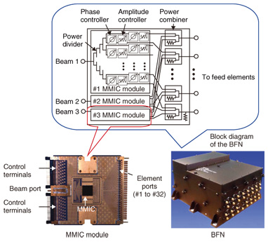
The large deployable antennas and multibeam-forming network technologies were jointly developed by JAXA (Japan Aerospace Exploration Agency), NICT (National Institute of Information and Communications Technology), and NTT. NTT Access Service Systems Laboratories has collaborated in the configuration and deployment analyses of the deployable antennas and has developed the beam-forming network (BFN), one of the main onboard systems. 2. Beam forming networkThe onboard multibeam antenna concept of the ETS-VIII is shown in Fig. 2. The antenna consists of many amplifiers, feed elements, and the BFN. This system is called a phased array. The BFN controls the amplitude and phase of the input signals for all feed elements in order to form the beam at the desired positions. A block diagram of the developed BFN is shown in Fig. 3. The BFN distributes the input signal to the 31 feed elements of the ETS-VIII and suitably controls the amplitude and phase of each signal.
All of the satellite onboard equipment is required to be compact and lightweight due to the limitations of rocket launching. To reduce the size and weight of the BFN, we designed a large-scale monolithic microwave integrated circuit (MMIC). One MMIC consists of 31 power dividers and 32 phase/amplitude control circuits. The size and weight of the BFN using MMICs are 250 mm × 266 mm × 155 mm and 7.4 kg, respectively; both are 50% smaller than the corresponding values for a conventional design [1]. In addition, the BFN can change the beam position and coverage area in response to commands transmitted from an earth station. 3. In-orbit verification of BFNIn-orbit testing of the BFN, which means design validity of the antenna system including the BFN, can be achieved by making antenna pattern measurements. The conventional antenna pattern measurement scheme, shown in Fig. 4, is to measure the signal level at one fixed scanning point on the earth while the satellite's attitude is changed. However, this requires a large number of attitude steps and takes a long time. Moreover, a large-scale lightweight onboard antenna like that on the ETS-VIII suffers from significant thermal deformation due to the thermal conditions in orbit. Since the thermal conditions change continually with the direction of the sun, antenna pattern measurements should be completed within a short period i.e., less than six hours.
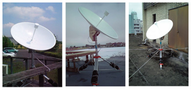
We devised a new method that can rapidly measure antenna patterns. In our method, the signal from the satellite is received simultaneously at several observation points. By optimizing the locations of the observation points, we were able to significantly reduce the number of attitude control steps needed. We also devised a new technique that can decrease the measurement error at each observation point [2]. We used these methods to measure the antenna pattern of the ETS-VIII and perform in-orbit verification of the BFN's capabilities 4. Test resultsWe tested the BFN in orbit at the end of March 2007 and from the end of May to the middle of June 2007. The initial checkout in March was intended to verify the control command system such as on-off control of the power to the BFN and the function for monitoring BFN conditions such as its on-off status, temperature, and amplitude/phase control values. A more precise verification was started in May when the satellite began normal operations after the initial checkout. We also measured the antenna pattern of the beam covering the Kanto-Tohoku area of Japan, one of the five beams shown in Fig. 1. The BFN control parameters needed to form the beams were calculated at NTT Yokosuka R&D Center and then transmitted to the satellite. Satellite attitude control was executed by the JAXA Tsukuba Space Center, the satellite's developer. Onboard system control was implemented by the NICT Kashima Space Research Center. We chose five observation points to measure the antenna pattern, where the distances between the observation points in terms of latitude were equivalent from the view of the satellite. The measurement environments of the observation points are shown in Fig. 5. We measured the signal reception levels with 1.2-m parabolic antennas. The measurement results, shown in Fig. 6, overlay the five beam patterns. Red lines indicate the contour of -3 dB against the peak gain, i.e., the service area. For Kyushu and Shikoku, additional contours for -10 and -20 dB are shown; they confirm that no unnecessary radio signals were transmitted. Consequently, we verified the prescribed beam forming at the calculated positions and proper operation of the BFN. Moreover, the measurement time taken using our method was about 6.5 hours per beam, which is about 75% shorter than with the conventional method.
5. Conclusion and future workWe verified that the BFN developed for the ETS-VIII onboard system operated properly in orbit. This BFN will be utilized in further experiments conducted by the participating institutes. References
|
||||||||||||