|
|||||||||||||||||||||||||||||||||||||||
|
|
|||||||||||||||||||||||||||||||||||||||
       |
Special Feature: NGN Mobile Communication Technologies for Large-capacity and High-efficiency Communications in the Flat-rate Era Vol. 6, No. 11, pp. 10–18, Nov. 2008. https://doi.org/10.53829/ntr200811sf5 Overview of Super 3G (LTE) System and Experimental ResultsAbstractThis article gives a technical overview of Super 3G (also known as Long Term Evolution (LTE)) and presents the results of some experiments using trial equipment that demonstrate its effectiveness. 
1. Overview of Super 3G (LTE) radio systemThe basic specifications of the Super 3G equipment that we used for trials are listed in Table 1 [1]–[3]. These specifications agree with the LTE (Long Term Evolution) specifications in 3rd-generation Partnership Project (3GPP) standardization activities. The downlink uses orthogonal frequency division multiple access (OFDMA) providing high resistance to multipath interference and flexible support for a wide range of frequency bandwidths by changing the number of subcarriers. The uplink, meanwhile, uses single-carrier frequency division multiple access (SC-FDMA)*1, which can achieve low power consumption by decreasing the peak-to-average power ratio (PAPR)*2 of user equipment (UE) and reduce interference from other users by maintaining orthogonality in the frequency domain. The following outlines these radio access systems.
1.1 OFDMA downlink radio accessOrthogonal frequency division multiplexing (OFDM) achieves signal transmission robust to multipath interference (interference from delayed waves) through the parallel transmission of a high-data-rate wideband signal using multiple low-symbol-rate multicarrier signals. The OFDM scheme uses subcarrier signals with narrow bandwidths, which enables flexible support of a wide range of signal bandwidths by changing the number of subcarriers. It incorporates a guard interval called a cyclic prefix (CP) at the head of each symbol to eliminate symbol interference caused by the delayed wave of the previous symbol and inter-subcarrier interference caused by the destruction of the orthogonality between subcarriers (Fig. 1). The following describes important capacity enhancement technologies newly applied to Super 3G (LTE).
1) Frequency-domain packet scheduling In broadband transmission, the key to reducing the effect of frequency-selective fading, in which the received signal level fluctuates in the frequency domain due to multipath interference, is to make effective use of it. Super 3G (LTE) applies frequency-domain packet scheduling using fluctuations in the propagation path within the frequency domain as a data-channel transmission method. Here, UE measures, for each defined unit of frequency, the channel quality indicator (CQI) indicating the received signal quality on the downlink channel and reports the measured CQI to evolved Node B (eNB)*3, i.e., the base station, via the control channel on the uplink. The eNB, in turn, uses CQI information so obtained from multiple users as a basis for allocating radio resource blocks (RBs)*4 to selected users (Fig. 2). The optimal allocation to individual users of frequency blocks having high received signal levels in accordance with each user's CQI enables a diversity effect (multiuser diversity) to be obtained and user throughput and throughput per cell to be improved.
2) High-speed signal transmission using MIMO multiplexing transmission Multiple-input multiple-output (MIMO) multiplexing transmission achieves high-speed transmission by using multiple transmit and receive antennas to transmit and receive different signals on the same frequency at the same time, thereby improving user and cell throughputs. The mobile terminal separates transmit signals on the basis of measured channel fluctuation by using the antenna interval orthogonal reference signal*5 of each transmit antenna. In contrast to single-carrier radio access like direct sequence code division multiple access (DS-CDMA)*6, OFDMA can perform highly accurate signal separation with respect to other transmit antenna signals without being affected by multipath interference, making it highly compatible with MIMO multiplexing transmission and applicable to high-speed signal transmission. Also applied here is rank adaptation, which controls the number of transmit streams according to the receive conditions (Fig. 3). This control scheme improves quality by decreasing the number of transmit streams when the receive level is low or channel correlation is high, and it achieves high-speed transmission by transmitting multiple streams simultaneously when the receive level is high and channel correlation is low.
1.2 SC-FDMA uplink radio accessOne aspect in which the uplink differs from the downlink is that reducing power consumption at the mobile terminal is a vital requirement. In particular, given that the power amplifier in the transmit part of the mobile terminal consumes a large proportion of the power, it is essential to adopt an access system applicable to an amplifier with high power efficiency. Furthermore, assuming power amplifiers with the same maximum transmission power, the coverage area that can achieve the same receive performance can be enlarged by lowering the PAPR of the access scheme. It is for these reasons that Super 3G (LTE) adopts SC-FDMA. The following describes the main features of SC-FDMA radio access. 1) Variable bandwidth with SC-FDMA In the uplink, data channel transmission is performed at the minimum transmission power corresponding to the data rate of the traffic required from the viewpoint of reducing power consumption in the mobile terminal, as discussed above. We note here that increasing the transmit-signal bandwidth achieves a higher frequency diversity effect that averages out propagation-path fluctuations in the frequency domain. However, increasing the transmit-signal bandwidth above that which is necessary reduces the power density of reference signals needed for estimating the radio propagation path. As a result, performance at the receiver is degraded by poor channel estimation accuracy. This is the reason for using SC-FDMA, which supports variable bandwidth corresponding to the data rate of transmission traffic (Fig. 4). A particular point in which the uplink differs from the downlink is that the former allows the transmission of only a single carrier. Here, to maintain the properties of a single carrier, consecutive frequency bands (consecutive RBs) must be allocated by frequency-domain packet scheduling as opposed to discrete frequency bands. In addition, the application of frequency hopping, which allocates different frequency bands within a subframe or between subframes, enables a frequency diversity effect to be obtained and high-quality reception to be achieved.
2) Frequency-domain SC-FDMA signal generation Similar to the downlink, SC-FDMA radio access in the uplink allocates part of the system frequency band to each UE through frequency-domain packet scheduling. The scheme used here to generate SC-FDMA signals in the frequency domain is discrete Fourier transform spread OFDM (DFT-Spread OFDM). A block diagram of this scheme is shown in Fig. 5. The UE subjects the post-modulation data symbol sequence to DFT processing and maps the data symbols obtained as a result of this DFT processing to only the frequency band allocated to it while mapping 0s to the non-allocated frequency band. The resulting data sequence is then subjected to an inverse fast Fourier transform (IFFT)*7 to generate the transmit signal. An important feature of using DFT-Spread OFDM is that the same clock frequency and subcarrier spacing as OFDMA in the downlink can be achieved.
3) Frequency equalization using CP SC-FDMA radio access requires an equalizer to suppress interference from a delayed wave in its own channel (multipath interference). Equalization processing in the frequency domain is less computationally intensive than that in the time domain, making the former more practical to implement. This equalization processing requires that the time-domain signal be converted to a frequency-domain signal in units of blocks, and as a consequence, a CP is incorporated into each fast Fourier transform (FFT) block to eliminate the effects of inter-block interference. 4) Fractional transmission power control Since orthogonalization between users can be achieved in the frequency domain in SC-FDMA as described above, interference in CDMA does not occur within the same cell (sector). For this reason, fractional transmission power control (TPC) is applied to control the target value for each user's transmission power. Fractional TPC sets high target values for users located close to the base station to increase throughput and sets low target values for users close to the edge of the cell to decrease interference with other cells thereby improving overall throughput (Fig. 6).
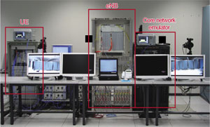
2. Super 3G trial equipment and experimental resultsThe Super 3G trial equipment that we have developed is aligned with 3GPP standard specifications and incorporates the functions covered in section 1. Section 2.1 outlines this Super 3G trial equipment and sections 2.2 and 2.3 present the results of radio transmission experiments using it. 2.1 Configuration of trial equipmentThe configuration of indoor trial equipment consisting of eNB, UE, and a core network emulator is shown in Fig. 7. The eNB and UE are connected using a fading simulator to emulate radio propagation paths. Data transferred from the core network emulator is first multiplexed with a header for radio control at the eNB and then converted from a serial to a parallel data sequence for each codeword*8. A codeword is a retransmission unit in the hybrid automatic repeat request (H-ARQ)*9 scheme and a maximum of two are used. Next, the bit sequence following serial-to-parallel conversion is subjected to channel coding, data modulation mapping, and multiplication by a precoding matrix, and a transmit signal for each antenna is generated. Channel coding applies turbo coding with constraint length = 4 and coding rate R = 0.16–0.89, and data modulation applies quadrature phase shift keying (QPSK), 16 quadrature amplitude modulation (QAM), and 64QAM. The maximum number of transmit antenna branches is four.
On the receiving side, the UE performs linear amplification and quadrature detection on the signal received at the four receive antenna branches by automatic gain control (AGC) and performs analog-to-digital (A/D) conversion of the I/Q (in-phase/quadrature) channel signal to a received digital signal. It then detects and updates the received OFDM symbol timing based on the correlation between the pre-FFT received signal and the orthogonal reference signal multiplexed within the frame. Next, based on the received OFDM symbol timing so obtained, the UE removes the guard interval in the received digital signal and separates the signal into subcarrier components by FFT. The UE then estimates the channel estimation value between transmit and receive antenna branches using the reference signal and then uses this value to perform signal detection in the signal separation part using maximum likelihood detection with QR decomposition and the M-algorithm (QRM-MLD) and adaptive selection of surviving symbol replica (ASESS) techniques [4], and it calculates the log likelihood ratio (LLR) of each bit for soft-decision turbo decoding in the LLR calculation part. Finally, the UE inputs the LLR for each bit into the turbo decoder (max-log-MAP decoding), performs a parallel-to-serial conversion on decoded data corresponding to each transmit antenna branch, and regenerates the transmit signal sequence.
2.2 Indoor experiment results1) Downlink throughput performance The experimental results for throughput performance versus the signal energy per symbol to noise power spectrum density ratio ES/N0 for one receive antenna when transmitting by one antenna with the modulation and channel coding scheme (MCS)*10 as a parameter are shown in Fig. 8. The bandwidth used here was 20 MHz, which is the maximum bandwidth of Super 3G (LTE), and the channel model was the extended Vehicular A 3 km/h*11. Also, for the purpose of comparison, the figure shows the results of computer simulations for the same channel model. The results in the figure show that the experimental results agree well with the simulation results, i.e., the loss in the required average received ES/N0 caused by the quantization error of A/D converters and the nonlinearity of the radio-frequency receiver circuitry including the AGC amplifier was less than 1 dB.
The throughput performance when transmitting by multiple antennas (MIMO) is shown in Fig. 9. Here, the number of transmit and receive antennas was four each and the number of transmit streams (rank number) was a parameter. The channel model was a six-path exponential decaying model whereby the average received power attenuated by 2 dB per path and the UE movement speed was 3 km/h. We also applied adaptive modulation and channel coding (AMC), which selects the optimal combination of modulation order and coding rate according to the receive level and H-ARQ, which retransmits packets in the event of errors and combines them at the receiver side. Incremental redundancy, which transmits different redundant bits to improve error correction performance during retransmissions was used as the H-ARQ scheme. Other conditions were the same as in Fig. 8, and the fading correlation between antennas was 0. The results in the figure show that a throughput of 100 Mbit/s was achieved for rank 2 for average received ES/N0 = 18 dB and that a maximum throughput of 240 Mbit/s was reached in a fading environment for rank 4.
2) Uplink throughput performance The experimental results for throughput performance versus average received ES/N0 with MCS as a parameter are shown in Fig. 10. The bandwidth used here was 20 MHz, the maximum bandwidth of Super 3G (LTE), and the channel model was extended Vehicular A 3 km/h, the same as in the downlink. The figure also shows the results of computer simulations for the same channel model for the purpose of comparison. These results show that the experimental results agree well with the simulation results, i.e., the loss in the required average received ES/N0 is within 1 dB.
The throughput performance versus normalized propagation loss from the eNB is shown in Fig. 11. In the experiment, we used the Okumura-Hata formula to calculate normalized propagation loss with respect to distance from the eNB and we adjusted the signal attenuation level to evaluate throughput performance as a parameter equivalent to distance from eNB. The figure shows normalized values such that propagation loss at a point 35 m from the eNB was 0 dB. The maximum UE transmission power was taken to be 24 dBm and parameter NRB denotes the number of RBs used (allocated bandwidth). In addition, we used fractional TPC for transmission power control and set the transmission power according to the propagation loss, and we applied AMC and H-ARQ, the same as in the downlink. Examining the results in the figure, we can see that applying a bandwidth of NRB = 96 (17.2 MHz) in the vicinity of the cell enabled a throughput of about 50 Mbit/s to be achieved, while decreasing the number of RBs allocated to users at the edge of the cell could increase coverage.
3) Delay performance The configuration of a delay measurement experiment for testing the shortening of transmission delay, one of the most important technical requirements in Super 3G (LTE), is shown in Fig. 12, and the round-trip transmission delay values as measured using a ping command are shown in Fig. 13. Round-trip transmission delay was found to be about 12–13 ms, and taking into account the transfer delay between the eNB and server and the processing delay at the core network emulator and server, these results indicate that the 5-ms one-way transmission delay target of Super 3G (LTE) is practically satisfied.
2.3 Field trial resultsField trials commenced in February 2008 in two areas: Yokosuka City in Kanagawa prefecture and Kofu City (and its suburbs) in Yamanashi prefecture. The field trial course in Yokosuka City is shown in Fig. 14. In this area, we tested radio performance for actual radio propagation channels. A screen shot of field trial performance, and in particular, receive performance of the downlink when transmitting from four antennas on the eNB is shown in Fig. 15. It was confirmed that a throughput of about 250 Mbit/s was achieved even in a field-trial environment.
3. ConclusionIn this article, we described the state of development of Super 3G (LTE) and its performance in transmission experiments using trial equipment and demonstrated the effectiveness of the system. Now we are planning to test a frequency-domain scheduler function for simultaneously connecting multiple users and an inter-sector and inter-cell handover function, to perform tests toward practical deployment, and to work on optimizing the system. References
|
||||||||||||||||||||||||||||||||||||||