 |
|||||
|
|
|||||
|
Letters Vol. 7, No. 2, pp. 28–34, Feb. 2009. https://doi.org/10.53829/ntr200902le1 Expansion of Applicability of Multiple Cabling TechnologyAbstractTo prevent congestion in underground conduits caused by the continued growth in demand for optical services, we have developed a small-diameter 1000-core optical cable and technology for expanding the applicability of the inner pipe method to accommodate 3000 fibers in a conduit.
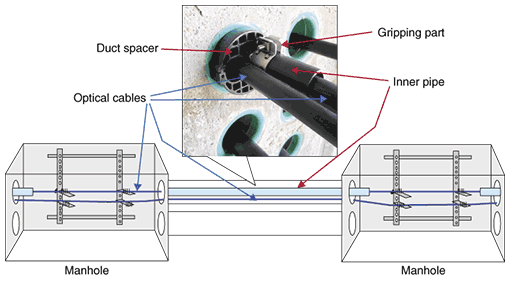
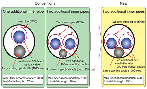
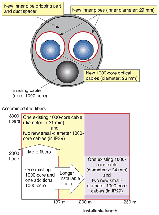
1. IntroductionFiber-to-the-home (FTTH) service is now in the growth stage and has become the main type of broadband service in Japan. Recent figures show that the number of new FTTH subscriptions is about 300,000 per month, whereas DSL (digital subscriber line) use is decreasing rapidly. The entire NTT Group is working hard to expand optical services with a view to achieving 20 million optical access subscribers by 2010. Our research and development section is working on technological developments that will ensure that optical access networks are not only economical, functional, and of high quality, but also available as soon as they are required. We expect optical demand to grow through the commercialization of Next Generation Network (NGN) services and the development of this area in the future. Therefore, a lot of cable will need to be installed. As a result, we are concerned about congestion in underground ducts [1]. This article introduces a small-diameter 1000-core optical cable and technology that we have developed to expand the applicability of the inner pipe method for cable installation in conduits. These developments make it possible to accommodate 3000 fibers in a conduit, use the existing infrastructure efficiently, and improve the efficiency of investment in underground infrastructure facilities. 2. Development conceptsThe inner pipe method was established to utilize existing conduits effectively. Inner pipes are installed in conduits that already accommodate existing cables, and new optical cables are then installed in inner pipes (Fig. 1). As shown in Fig. 2, if we use two additional conventional inner pipes (IP30), we can accommodate only 1000 fibers in a conduit. If we use one larger additional inner pipe (IP36), we can still accommodate only 2000 fibers in a conduit. Moreover, limitations on installation tension mean that the maximum length of additional inner pipes that can be installed in a straight conduit is only 137 m for a single pipe or 78 m for two pipes. This limits the applicability of conventional multicable installation.
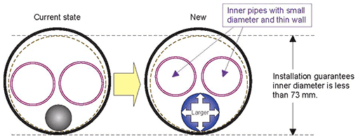
We have developed a new small-diameter 1000-core optical cable and a new small-diameter inner pipe (IP29). They were designed to expand the applicability of the inner pipe method, reduce the initial construction investment needed to increase the number of conduits, shorten the construction period, improve optical facility operation by making it possible to accommodate 3000 fibers in a conduit, and extend the installation length. 3. New developments3.1 Inner pipe (IP29)The maximum number of fibers in one underground optical cable is 1000. Thus, to accommodate 3000 fibers in a conduit, we must install two additional inner pipes that can accommodate two 1000-core cables in a conduit that already contains an existing 1000-core cable. The new method must accommodate a large existing first cable and the additional inner pipes must have a small outer diameter and thin wall to accommodate the additional 1000-core cables and still fit in the conduit (Fig. 3). Moreover, to increase the installation length of the inner pipe, we must reduce both the pipe’s weight and friction coefficient. Fortunately, a thinner wall satisfies the former requirement and a smaller diameter satisfies the latter.
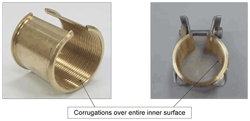
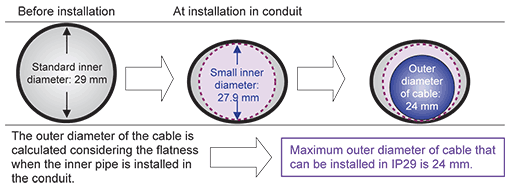
Our new inner pipe (IP29) will be used in place of conventional inner pipe (IP30) in the case where two additional inner pipes are installed. Various construction experiments designed to measure construction tension led to the following dimensions being chosen for IP29: outer diameter of 33 mm, wall thickness of 2 mm, inner diameter of 29 mm, and unit weight of 0.18 kg/m (representing reductions of 3 mm in outer diameter, 1 mm in wall thickness, and 0.1 kg/m in unit weight compared with IP30). The dimensions of IP29 let us accommodate a large existing cable and enable two inner pipes to be installed and later removed simultaneously as usual. Moreover, IP29 supports a longer installation length. When the existing cable has a diameter of less than 24 mm, up to 250 m of twin IP29s can be installed in a straight conduit. 3.2 Gripping part and duct spacer for IP29We changed the shape of the gripping part and the duct spacer. These developments are based on the concept of accommodating an existing cable having a maximum outer diameter of 31 mm and two IP29 inner pipes. Because IP29 has a thin wall, the conventional holding method would cause the pipe to buckle and deform. Therefore, we changed the holding method from a fingernail-type grip to corrugations over the entire inner surface (Fig. 4). This method holds the inner pipe without deforming it.
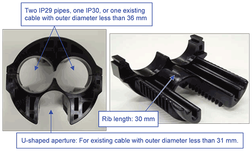
As shown in Fig. 2, the conventional twin-IP30 method only works with a small existing cable (max.: 200-core). To enable our new twin-IP29 method to work with a large existing cable (e.g., 1000-core), we had to design a new duct spacer with a larger U-shaped aperture. The holes for the inner pipes and the reduced amount of material around the U-shaped aperture mean that the duct spacer has less structural material, which consequently reduces its rigidity. Therefore, we increased the length of the rib to provide greater strength (Fig. 5). This allows us to standardize on one duct spacer that can be used for either the conventional or new inner pipes, which will reduce costs.
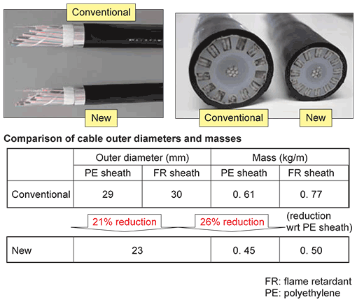
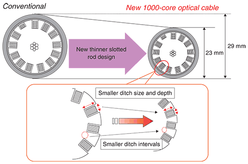
3.3 New optical cableBecause we must consider inner pipe flatness when a pipe is installed in a conduit, the diameter of the new cable designed to go in the new inner pipe (IP29) should be considered in terms of the inner diameter of the flattened IP29. The outer diameter of the new 1000-core cable was designed based on this requirement: the maximum value is 24 mm (Fig. 6). The structures of the conventional and new 1000-core optical cables are compared in Fig. 7. Conventional 1000-core optical cable has a diameter of 29 mm. To get a smaller outer diameter, we needed to design a new thinner slotted rod to accommodate the optical fiber tape. Moreover, this rod’s diameter had to be reduced in order to reduce the ditch size, depth, and intervals (Fig. 8) without affecting fiber extraction work etc. while guaranteeing that the cable characteristics are at least as good as those of the conventional cable. The new small-diameter 1000-core cable incorporates the following technologies.
Using these technologies, we achieved an outer cable diameter of 23 mm using the same 13-slot structure as in conventional cable.
4. SummaryOur new technologies enable 3000 fibers to be accommodated in one conduit (Fig. 9). This should lead to improved investment efficiency for underground infrastructure facilities and reduce congestion in conduits. We plan to develop technologies that will contribute to faster installation work, more effective use of existing facilities, cost reduction, and the provision of functions for achieving NTT’s target of “optical access for 20 million subscribers by 2010”.
Reference
|
|||||


