 |
|||||||||||||||||
|
|
|||||||||||||||||
|
Special Feature: NTT Group R&D for Reducing Environmental Load Vol. 7, No. 10, pp. 14–18, Oct. 2009. https://doi.org/10.53829/ntr200910sf3 Solid Oxide Fuel Cell Stack with High Electrical EfficiencyAbstractThis article introduces the development of a solid oxide fuel cell (SOFC) stack with anode-supported cells. The SOFC can provide the highest electrical efficiency among all fuel cell types, and high electric efficiency leads to less CO2 produced during power generation.
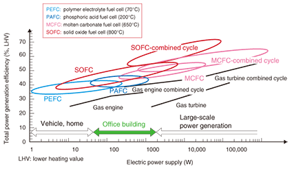
1. IntroductionIn our daily lives, we use a lot of electric cells, for example, primary cells such as dry cells and alkaline cells and secondary cells such as lead acid batteries, nickel cadmium batteries, nickel metal hydride batteries, and lithium-ion batteries. Fuel cells are not electric cells, but electric generators. A battery is a storage system that can be used only when charged with electricity. However, a fuel cell is a system that produces electric power through direct reaction between oxygen and a fuel such as natural gas, liquefied petroleum gas, or kerosene. Thermal-electric power generation also uses the same fuels as fuel cells do, but several steps are needed to produce electricity: burning fuels, obtaining their heat energy, driving a turbine by this heat energy, and finally producing electricity from the turbine’s kinetic energy. Therefore, the overall conversion efficiency is not always high because it is the product of the individual efficiencies. Since a fuel cell has only one conversion step, its efficiency tends to be high. Fuel cells usually use fuels derived from carbon-based fuels (also called hydrocarbon fuels and fossil fuels). Some fuel cell systems under development and other electric generator systems are shown in Fig. 1. One fuel cell that has entered practical use is the polymer electrolyte fuel cell (PEFC), which is the basis for the world’s first residential fuel cell cogeneration system called ENEˇ¦FARM. However, the most promising fuel cell in terms of conversion efficiency (for converting fuel energy to electrical energy) is the solid oxide fuel cell (SOFC). That is why we are focusing on developing SOFCs.
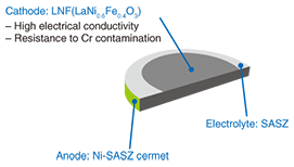
2. SOFCThe SOFC has high electrical efficiency, which means that it creates less CO2 than conventional generators. An SOFC operates at a temperature ranging from about 700 to 1000ºC, which is much higher than that of the PEFC (70ºC). This high operating temperature means that the materials used for the SOFC must be highly heat resistant, which is a major technical difficulty. 2.1 CellsIn a fuel cell, the cell is a device for producing electric current from the chemical reaction between oxygen and hydrogen, which react in the presence of an electrolyte. For SOFCs, various types of cells are under development. We are focusing on a higher power density at the electrodes and developing planar anode-supported cells [1]. A cell that we have developed is schematically shown in Fig. 2. For the cathode material, we have developed lanthanum nickel ferrite (LaNi0.6Fe0.4O3: LNF), which provides high electrical conductivity and almost the same coefficient of thermal expansion as the electrolyte and is resistant to chromium contamination. The electrolyte, which lies between the cathode and anode, conducts oxygen ions from the cathode to the anode during electrical generation. For the electrolyte, we chose to use scandia-alumina stabilized zirconia (SASZ) because of its high ionic conductivity. For the anode, we chose a cermet of metallic nickel and SASZ. The cell constructed of these materials provides a high power density of 1.6 W/cm2, which is one of the best performances in the world. We have developed a 120-mm-diameter cell that has this power density.
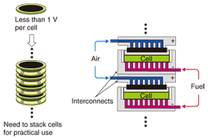
2.2 Stack2.2.1 OverviewThe voltage produced by one cell during electrical generation is only 0.6–0.8 V. Therefore, a fuel cell system consists of multiple cells connected in either series to provide the required voltage or in parallel to provide the required current. This configuration of connected cells is called a stack. A stack of series-connected cells is illustrated in Fig. 3. The stack feeds all the cathodes with oxygen and all the anodes with fuel. The interconnects provide a conductive path between adjacent cells and also carry oxidant or fuel gas. The performance of the stack is dominated by the interconnect design and the interconnect-cell interface design. A stack is fabricated from different materials such as metals and ceramics. Another major factor affecting stack performance is the gas seal, which is needed to prevent the escape of gas. All the materials used in a stack must have almost the same coefficients of thermal expansion and be unreactive with the cell.
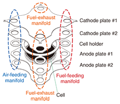
We developed our SOFC stack by trial and error by focusing on the abovementioned points. The repeating unit, or single cell unit, of our stack is shown in Fig. 4. It has the following characteristics.
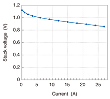
2.2.2 Single-cell stackA stack with only one cell unit is called a single-cell stack. The stack voltage versus the current (current-voltage profile) in the current range from 0 to 27 A when the fuel was hydrogen is shown in Fig. 5. The voltage at 27 A was 0.87 V, so the generated power was 23.5 W. We performed a durability test on the single-cell stack and found that it retained a power generation efficiency of about 60% for 7000 hours [2]. Next, we evaluated high-power stacks constructed from our single-cell units.
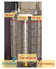
2.2.3 High-power stacks(1) 1-kW-class stack Since a single cell unit provides about 20 W, we fabricated a stack using 50 single-cell units to obtain a power output of 1 kW. The key points for success here were electrical contact, gas seals, and equal distribution of oxidant and fuel. The appearance of the 50-cell stack is shown in Fig. 6. We inserted intermediate plates every ten cell units. These rigid plates canceled out the cumulative position and angle errors of the stack parts and improved the electrical contact and gas seal.
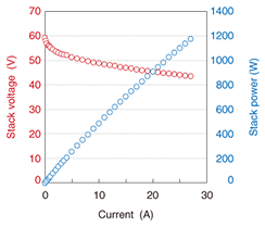
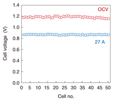
The current-voltage profile when the fuel was hydrogen is shown in Fig. 7. The voltage at 27 A was over 40 V and the electric power was nearly 1200 W. As shown in Fig. 8, the voltage of the 50-cell stack at 0 A (open circuit voltage) was 27 A. This result indicates excellent cell electrical contact performance and excellent equality of gas distribution.
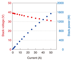
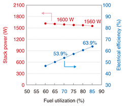
When the fuel was changed from hydrogen to methane-reformed gas (a mixture of H2, CO, CO2, and H2O produced from methane and steam in a reformer), the electric power of the 50-cell stack was still nearly 1200 W at 27 A. Generating efficiency tends to increase with fuel utilization (the percentage of fed fuel gas converted into electric current). When the fuel utilization was 67%, we obtained 1120 W of electric power with a high generating efficiency of 53.4%. (2) 1.5 kW-class stack We tried to reduce the size and improve the capabilities of the 50-cell stack. We decided to use 40 cells in the stack and aimed to achieve 1.5 kW by increasing the current. We also improved the electrical contact and gas seals. A current-voltage profile when the fuel was methane-reformed gas is shown in Fig. 9. The electric power of the 40-cell stack was about 1600 W at 50 A, and the stack voltage was over 30 V. The relationship between fuel utilization and generating efficiency is shown in Fig. 10. For fuel utilizations of 70% and 85%, the generating efficiencies were 53.9% and 63.9%, respectively. Furthermore, we determined that the degradation in stack voltage was less than 1% during 1000 hours of operation.
3. Concluding remarksWe have developed an SOFC stack using 120-diameter anode-supported cells that provides electric power of over 1.5 kW with high power generation efficiency of over 60%. We will apply our stack to SOFC modules or systems for practical use and also make further cell and stack improvements. Our goal is to reduce CO2 emissions from electric power generation by putting the SOFC system into practical use. Our SOFC stack can collect CO2 without O2 or N2, so CO2 stabilization is easier. We hope that our SOFC system will lead to a zero-emissions electric generator. We will strive to achieve our dream for a better future. References
|
|||||||||||||||||


