 |
|||||||||
|
|
|||||||||
|
Special Feature: ICT-based Risk Management and Business Continuity Management Vol. 8, No. 1, pp. 17–26, Jan. 2010. https://doi.org/10.53829/ntr201001sf3 Automatic Realtime Bridge Monitoring System (BRIMOS): Prototype Testing Before Service StartAbstractWe describe a prototype of a system for remotely monitoring a bridge in real time, which will provide valuable information for managing the response to a natural disaster, maintaining the bridge’s structure, and estimating the extent of structural fatigue. The bridge monitoring system (BRIMOS) consists of various sensors, high-speed data transmission networks, and an information center that collects and disseminates high-level information about the bridge’s performance. The prototype monitoring the Metropolitan Expressway in Tokyo was found to be both reliable and durable. On the basis of its results, a service using the BRIMOS system was started in September 2009.
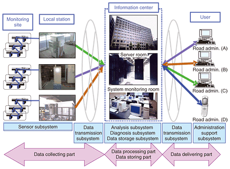
1. IntroductionHighway bridges in Japan have suffered various kinds of damage, e.g., fatigue, corrosion, and abrasion, which have been worsened by the continual passing of overloaded heavy vehicles. There is a risk of a serious disaster in the event of an earthquake or accident occurring in the vicinity of bridges that are already weakened through damage. If such a disaster were to occur in a densely populated area such as Tokyo, the effects could be severe. According to seismic experts, there is a high risk of a big earthquake occurring in Japan in the immediate future. In such an event, the establishment of secure road networks is a key factor for ensuring public safety and preventing economic loss. One of the most important pieces of information required is whether vehicles, especially emergency and transport vehicles bringing in relief supplies, can pass over a particular bridge or not. However, getting this information generally takes several hours because it is done by someone checking at the location. Therefore, if a monitoring system could remotely check the integrity of several bridges instantaneously and simultaneously, it would substantially reduce both social and economic losses. The interval between regular inspections of Japanese highway bridges is typically five years, which is often not frequent enough for early detection of damage and, if necessary, appropriate maintenance scheduling. A monitoring system that could automatically detect changes in the daily basic motions of bridges, e.g., the vibration of the girders, between regular inspections would enable maintenance to be scheduled well in advance of the next regular inspection. Information technology (IT) has already contributed greatly to the dramatic changes in how bridges are maintained, and it has enabled a large amount of data to be handled quickly and efficiently. This has mainly resulted from high-speed processing technology that enables data to be transmitted at high speed and stored in large amounts. We are developing a bridge monitoring system (called BRIMOS) that is based on the use of advanced IT to automatically monitor bridge motion. This motion data enables road/bridge administrators to evaluate the status of a bridge. The system’s various sensors, e.g., video cameras and optical fibers, continuously monitor several of the bridge’s daily motions and thus provide instant updates of unavailability caused by either abnormal loads, e.g., seismic ones, or routine loads, such as those caused by daily traffic flows. A prototype system was developed for the Metropolitan Expressway in Tokyo to clarify system performance. 2. System design concepts2.1 System structureOur system provides all the monitoring results for users in real time, and the user can get an instant alert if the results are abnormal. This system consists of four parts composed of six subsystems (Fig. 1). The data collecting part at each monitoring site measures bridge motion using sensors and transmits the raw data to the information center. The data processing part generates value-added information from the raw data, and the data storing part stores both the raw data and the value-added information. The data delivering part acts as a data and information provider for users.
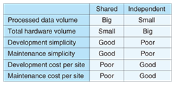
One of the key advantages of our monitoring system is the concentration of data processing and storage; i.e., we use a shared information system based on advanced IT. The underlying concept is that minimally processed raw data is transmitted directly from each local station to the information center, and the data is processed using shared resources, i.e., software and hardware. The information center covers a very wide area if the data transmission subsystem is between the sensor subsystem and the information center. Namely, there is no detrimental effect, e.g., reduction in processing speed, caused by having too many bridges and/or having them too far apart. The characteristics of the shared information system and a traditional independent one are compared in Table 1. The shared information system has enabled us to decrease the center-cost per site as the number of the monitoring sites has increased. The information center is constructed in a highly durable anti-seismic building equipped with several high-power generators.
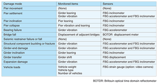
2.2 Monitoring planOur monitoring system meets three vital requirements for bridge management: disaster management, maintenance, and fatigue estimation. To make an optimized monitoring plan for each purpose, i.e., to get enough information for each purpose by using as few sensors as possible, we use a fault tree analysis, which is an effective way to clarify the relationship between the bridge’s behavior and its damage modes [1]–[3]. The first step was to design our monitoring plan on the basis of a previous study [3], which in turn was based mainly on data from the Great Hanshin-Awaji Earthquake (1995). A fault tree analysis is used for managing the response to a disaster and future maintenance. As fatigue is mainly induced by the live load of heavy vehicles, the weights, types, and number of vehicles are estimated. The next step, deciding how to deploy the sensor subsystem, was decided on the basis of the monitoring plan described above because it would have been too costly to deploy a range of sensors on all bridges in the area we investigated. The relationships between the damage modes, which are described elsewhere [3], the monitoring items, and the sensors to be used are given in Table 2. Note that each sensor can be used for both disaster recovery and maintenance management.
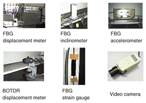
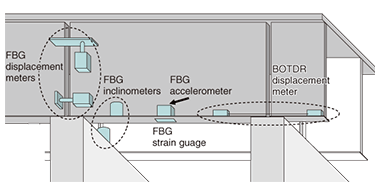
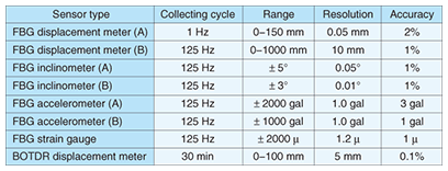
To estimate the extent of fatigue, we should select only one bridge on each route because the traffic of heavy vehicles is the only item to be detected. If the route is a beltway, the bridge to be monitored should be near a main junction. Moreover, since the sensor subsystem is extremely simple, implementing it on only one bridge on each route makes it cost effective. 2.3 Data collectionPhotographs of the different types of sensors are shown in Fig. 2, sensor attachment examples are schematically shown in Fig. 3, and the sensor subsystem specifications are listed in Table 3. Only fiber-optic sensors are used because they have higher durability because they do not use electricity. These sensors, with the exception of the fiber Bragg grating (FBG) strain gauge, have been developed recently and are well suited for long-term continuous monitoring of bridge motion because they are small (< 10 × 10 × 10 cm3) and durable. To clarify their performance, we tested two sensors with different specifications under different operating conditions.
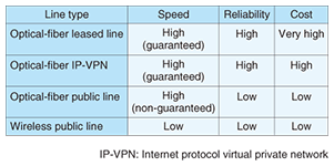
The raw wavelength data measured using the sensor subsystem is automatically transmitted to the data analysis subsystem via the data transmission subsystem after it has been converted into transmittable data at the local station, which has uninterruptible power supplies, located near the monitoring points. The type of data transmission line to be used can be selected to meet the needs set out by the road/bridge administrator in accordance with requirements for speed, reliability, cost, etc. The characteristics of the major transmission lines are listed in Table 4. We used an optical-fiber Internet protocol virtual private network and optical-fiber public lines to clarify the performance and cost effectiveness.
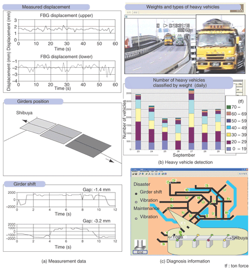
2.4 Data processing and storageThe data analysis subsystem changes the raw wavelength data transmitted from the sensor subsystem into a physical value, e.g., displacement or strain, and then automatically calculates each monitoring item shown in Table 2 and its time-period statistics, e.g., daily maximum, average, and minimum leaning of a bridge pier. The next step is for the diagnosis subsystem to ascertain the normality of the physical value by comparing them with the known thresholds calculated in advance using data gathered over a long monitoring period. The thresholds are determined using the occurrence rate, e.g., under 5%: abnormal, 5–10%: subnormal, over 10%: normal. The normality level is the first piece of warning information delivered to the road/bridge administrators. The raw wavelength data, physical values, and normality levels are stored in the database and can be retrieved from it at any time. 2.5 Data deliveryThe physical values and normality levels are presented in visual form by the administration support subsystem to help road/bridge administrators decide on the next action. In this work, a dedicated personal computer at a road/bridge administrator’s office was used to check the subsystem’s performance. The data display is shown in Fig. 4(a). It is updated periodically as set out in the data collection cycle. An example of realtime detection of heavy vehicles and a histogram of the number of vehicles of various weights passing over the bridge is shown in Fig. 4(b). The display representation of the normality level is shown in Fig. 4(c). It is shown on a 2D map with different colors corresponding to different normality levels.
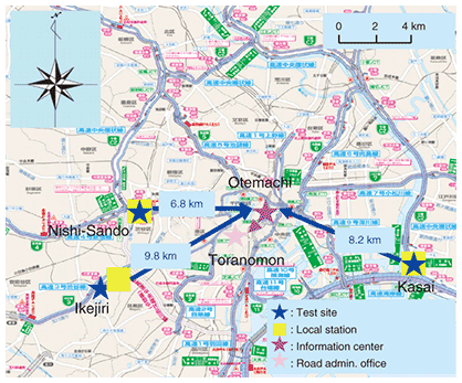
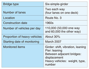
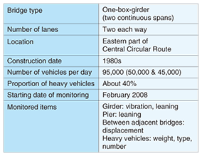
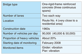
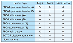
3. Evaluation of developed monitoring systemA prototype system was developed and set up on the Metropolitan Expressway in Tokyo to evaluate the system’s reliability and durability. 3.1 Test site characteristics and monitoring itemsThe locations of the information center (in Otemachi) and three test sites (bridges in Ikejiri, Kasai, and Nishi-Sando) are shown in Fig. 5. The site characteristics and monitored items for each site are listed in Tables 5–7, and the number of deployed sensors is listed in Table 8.
Each site is located on a route that carries some of the heaviest traffic in the Tokyo metropolitan area. Each bridge is subjected to the passage of many overloaded heavy vehicles. The bridge at the Ikejiri site requires constant maintenance, so we deployed many sensors on it. Even though the bridge at Kasai also suffers serious damage, we deployed fewer sensors there to better judge the suitability of our method for estimating vehicle weights and types for various bridge types and to clarify the performance with different sensor subsystem specifications. Only FBG accelerometers were deployed at the Nishi-Sando site because it is located very close to a residential area, and such areas tend to be strongly affected by vibration. 3.2 Data transmission experimentsThe data transmission types used in our system are listed in Table 9. The difference in cost between the most expensive and the cheapest is 50%. We checked their speed and reliability to clarify cost effectiveness. During our feasibility study, though no major earthquakes occurred, there were no problems with either speed or reliability. Therefore, the cheaper network might be suitable for daily use. In addition, we clarified the effect of the length of fiber from the sensors to the local station by adding a 5-km dummy fiber at the Ikejiri site. Up to the time of writing, there has been no trouble.
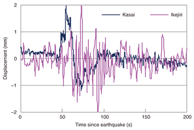
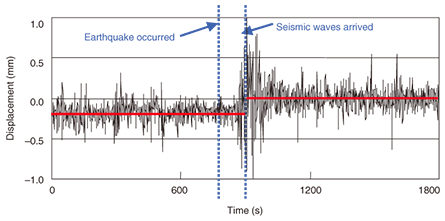
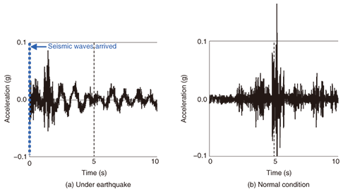
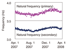
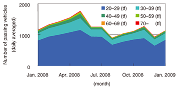
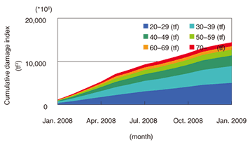
3.3 Monitoring resultsThis feasibility study provided a great deal of interesting information. The displacement between adjacent bridges at both Ikejiri and Kasai before and after the earthquake on May 8, 2008 is shown in Fig. 6. The frequency pattern was definitely different; i.e., there was a longer period at the Kasai bridge because it is larger. The displacement between adjacent bridges at Ikejiri before and after the Niigataken Chuetsu-oki Earthquake in 2007 is shown in Fig. 7. We found residual displacement after the earthquake. An example of how the vibration characteristics can change during an earthquake is shown in Fig. 8, which shows the vertical acceleration of a girder in the Ikejiri bridge. A long-period wave was observed during the earthquake. An example of the change in vibration characteristics during a year is shown in Fig. 9, which shows the natural frequency of vertical girder vibration measured with an FBG accelerometer on the Ikejiri bridge. With the exception of temperature-related changes, no remarkable changes appeared during the year. The long-term change in the number of heavy vehicles per month classified by weight is shown in Fig. 10 and the cumulative damage index caused by the heavy vehicles is shown in Fig. 11, which indicates that the small number of overloaded heavy vehicles causes more damage than the large number of other vehicles, i.e., bridge deterioration is mainly due overloaded heavy vehicles, despite their small number.
4. ConclusionThe system we have developed has been in operation since March 2007 and, although there have been no major earthquakes since then that would have subjected it to more rigorous testing, it has operated without any problems. The feasibility study clarified that the system is reliable and durable, so we began an information providing service based on this system in September 2009. From the viewpoint of the user (i.e., road/bridge administrator), the system’s cost effectiveness must be clarified before it can be widely implemented. Therefore, we plan to evaluate its cost effectiveness and make improvements that will further reduce its hardware and running costs. AcknowledgmentsThis article described research conducted in a cooperative study performed with the Metropolitan Expressway Co. Ltd, Professor Eiichi Sasaki of Yokohama National University, and Professor Chitoshi Miki of Tokyo Institute of Technology. References
|
|||||||||


