 |
|||||||
|
|
|||||||
|
Regular Articles Vol. 9, No. 4, pp. 52–56, Apr. 2011. https://doi.org/10.53829/ntr201104ra3 Development of Aerial Optical Closure for the High Demands of FTTH ServiceAbstractNew components have been developed to enable aerial optical closures to accommodate a larger number of splitters. The maximum capacity has been increased from four to eight. This development will reduce aerial facility congestion and cut construction costs.
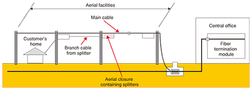
1. IntroductionThe number of broadband subscribers in Japan reached 34 million in September 2010. Of these, around 19 million, or more than 56% of the total, were fiber-to-the-home (FTTH) subscribers [1]. In response to the diversification and spread of FTTH services, we have studied conventional and new aerial optical closure components with a view to improving the splitter accommodation capacity [2]. 2. Development overviewTechnologies that enable a huge number of optical facilities to be efficiently and economically operated and maintained are needed. In the usual configuration used for providing FTTH services to residential premises in Japan, a customer’s home is connected to a central office via a splitter installed in an aerial closure (Fig. 1). For construction and maintenance efficiency, several splitters are installed in one place, i.e., in a single closure. The maximum number of splitters being installed in existing aerial closures is four. However, more and more splitters are being installed in Japan because of the recent increase in optical service demand and service diversification. As a result, many aerial optical closures are already full and cannot accommodate any more splitters. Therefore, additional aerial optical closures and cables frequently need to be installed, but this involves high construction costs.
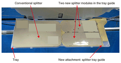
2.1 Design goalsTo cope with this problem, we identified the problem with conventional closures and set new design goals. The conventional aerial optical closure contains a certain number of trays: the number is chosen and fixed at the time of closure installation according to the predicted demand. It can accommodate four splitter modules if the maximum number of trays (two) are installed. Our design goals for the new aerial optical closure were to (1) design a new closure that can accommodate a larger number of splitter modules, (2) design components that can be installed in conventional aerial optical closures as well as in the new one, and (3) ensure that a field worker can install the larger number of splitter modules in a closure with the same ease. 2.2 Development resultsWe increased the number of splitter modules that can be installed from four to eight by developing smaller splitter modules that can also fit in a conventional closure. We increased the number of connections from a main cable to branch cables from 32 to 64 by developing components that let us double the number of branch cable connections in a closure space of the same size while still being compatible with conventional trays. As a result, we increased the number of main cable connections from 8 to 16. Since the number of main cable connections increases as the number of installed splitter modules increases, we developed components that allow the number of main cable connections to be increased when required. 3. Development detailsThis section describes the new aerial optical closure components in more detail. 3.1 Splitter moduleTo increase the number of splitter modules in a closure we had to develop a smaller splitter module that can be installed by using the free space in a conventional tray more effectively. In collaboration with the splitter module development department, we examined the basic structure. As a result, a new splitter module that is only 40% of the volume of the conventional one was developed. 3.1.1 New splitter modules in conventional trayWe developed an attachment (splitter tray guide) that can accommodate two of the new splitter modules in the space available previously occupied by one old splitter. Since two of these new attachments fit in a conventional tray, a conventional tray can accommodate four new splitter modules instead of two (Fig. 2). One feature of this attachment is that it can be used in either the right or left half. The bottom cover of the attachment prevents any sagging of the splitter cord.
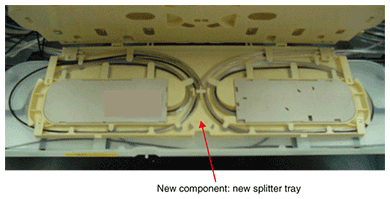
3.1.2 New tray optimized for new splitter modulesInstalling a splitter that uses two conventional trays and attachments increases costs, so we developed a splitter installation component (new splitter tray) for accommodating the new splitter modules. It has a two-layer structure: each layer can house two new splitter modules (Fig. 3). This component facilitates installation work by optimizing the positions of the new splitter modules.
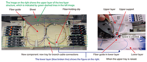
3.2 New tray for branch cable connectionsTo increase the number of splitters that can be installed, we doubled the connection capacity of the conventional aerial optical closure. To achieve this, we developed a component (a new tray for connections with branch cables) that can accommodate twice as many branch cable connections in the same space (Fig. 4). Moreover, it is compatible with the conventional branch cable tray. With the conventional one-layer tray structure, the fibers are congested. Our new two-layer structure makes it possible to connect 16 fibers: each one-layer tray for branch cable connections can connect 8 fibers, which prevents congestion. To ensure that fibers are not bent too tightly, we choose the locations of the new and existing connector connections to be different. As shown in Fig. 4, the fixed positions of the eight connectors in the upper layer and of the eight connections in the lower layer are out of alignment: this ensures that each optical fiber has a sufficiently large radius of curvature. On the basis of further feedback from field engineers, we designed a two-layer structure that incorporates measures to prevent fibers catching during field work. Fiber-holding clips were placed at appropriate positions. Furthermore, we redesigned the shape of the fiber guide. We designed the fiber guide configuration by enlarging the fiber-holding clip and we curved the fiber guide. As a result, the fibers are unlikely to pop out. The height of the fiber guide is set to be lower than the upper support. The fiber-holding section between the top and bottom layers must have sufficient space to prevent a fiber catching when the top and bottom layers are closed. Next, we created the fiber holding space using a conventional plastic case design. However, the resulting double-decker design was too thick and we could not make it the same size as the conventional case. Therefore, we decided to create a thin sheet to form the fiber-holding section. This sheet is hinged so that it normally lies flat against the case and cannot be removed. This design prevents the sheet from falling out during field work. The sheet is a self-supporting structure that stays open by itself during field work, so it does not impede the field worker. Sheets are provided for both layers; they act as lids that prevent the case from catching the fiber.
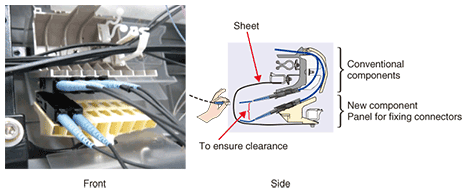
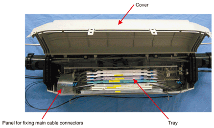
3.3 Panel for fixing main cable connectorsThe number of main cable connections increases as the number of installed splitters increases. Therefore, we developed a component (panel for fixing connectors to a main cable) that allows the number of main cable connections to be increased when required (Fig. 5). We decided to place the additional components in the vacant space below the existing ones because it was difficult to make drastic changes to the existing positions considering the fiber’s extra length. Since that would leave no space between the conventional and new components, there might be contact between the conventional and new component connectors. To ensure clearance between them, we gained space by setting the new component connectors at the maximum possible angle to the conventional ones. As a result, we faced the new worry that the cord from a connecter connected to a new component might get pinched when the cover is opened and closed (Fig. 6). However, we were able to protect the cords by attaching a sheet to the new component.
4. Concluding remarksWe have developed new components to increase the number of splitter modules that can be accommodated in aerial optical closures. They effectively utilize the free space in the current aerial optical closure and enable eight splitter modules to be accommodated in both the conventional and new closures. Workability is not reduced even in a high-capacity aerial optical closure. This development overcomes congestion in closures and will allow us to reduce construction and operating costs for the FTTH service. References
|
|||||||


