|
|||
|
|
|||
       |
Feature Articles: NTT Tsukuba Forum 2010 Workshop Lectures Vol. 9, No. 5, pp. 23–28, May 2011. https://doi.org/10.53829/ntr201105fa3 Current and Future Research on Optical Fiber and Cables AbstractThis article introduces the organization, research group topics, and R&D directions of NTT Access Network Service Systems Laboratories, which is researching and developing a full range of access-system technologies with a focus on optical fiber and cables. 
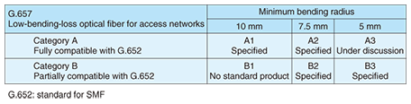
1. IntroductionNTT Access Network Service Systems Laboratories is fully engaged in the research and development (R&D) of access-system technologies. In particular, the Access Media Project extracts core technologies from themes selected through strategic studies, researches and develops those technologies, and passes on the R&D results to various promotion projects. In short, it exclusively handles the R&D of core technologies considered necessary for future systems. The Access Media Project consists of four groups. Some of the topics they are working on are described in more detail in section 2. (1) Media Utilization Group: next-generation outdoor optical line technology (2) Media Maintenance Group: optical line testing technology, media network management and operation technology, and preventive maintenance technology (3) Advanced Media Research Group: new optical fiber structures (4) Media & Equipment Monitoring Group: media measurement technology 2. Research topics by group2.1 Bending-loss insensitive fiber (Media Utilization Group)One consequence of the rapid penetration of fiber-to-the-home (FTTH) services is that many unskilled workers have came to be involved in the deployment of optical fiber. As a result, optical fiber bending loss became a frequent occurrence in the field. This problem led to active development of bending-loss insensitive fiber. Standardization of optical fiber insensitive to bending loss is progressing as Recommendation G.657 in ITU-T (International Telecommunication Union, Telecommunication Standardization Sector). There are two categories according to compatibility with existing optical fiber specifications (G.652): Category A having full compatibility and Category B having partial compatibility (Table 1).
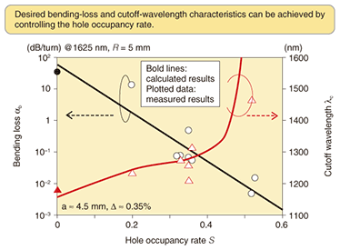
There are two approaches to decreasing bending loss: control the refractive-index distribution (optimal-refractive-index-distribution type of fiber) and form air holes (microstructured fiber). The former method controls the refractive-index distribution of existing single-mode fiber (SMF) to suppress bending loss, but its suppression effect is smaller than that of the latter method. The microstructured type, on the other hand, achieves large differences in refractive index within the optical fiber, which enables considerable design freedom. NTT has been using microstructured fiber for some time. It comes in various kinds such as hole-assisted fiber (HAF) and this type also includes nanostructured fiber. NTT has developed single-mode HAF design technology that simultaneously achieves single-mode transmission characteristics equivalent to standard SMF and low bending loss characteristics that greatly surpass the G.657.B.3 standard. The transmission characteristics of HAF can be easily determined from the area ratio of the hole section in the annular region of HAF (hole occupancy rate) and the core structure (core radius and refractive index). Bending loss decreases as the hole occupancy rate increases, but at the same time, the shortest single-mode wavelength (cutoff wavelength) increases, which prevents single-mode transmission from being achieved. Setting a hole occupancy rate of 0.3–0.4 yields optimal transmission characteristics for maintaining the cutoff wavelength while suppressing bending loss (Fig. 1).
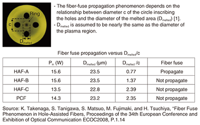
An example of HAF that can simultaneously achieve single-mode transmission characteristics and low bending loss has the following properties: hole occupancy rate of 0.41, bending loss (at 1625 nm, R=5 mm) of 0.04 dB/turn, cutoff wavelength of 1126 nm, and loss (at 1550 nm) of 0.19 dB/km. NTT is already providing free-bending optical fiber cord using HAF with a large bending-loss suppression effect. This cord can be deployed by ordinary people within their homes. Moreover, there are plans to extend single-mode HAF to NTT office facilities and other indoor and outdoor facilities with the aim of achieving even higher levels of transmission quality and reliability. 2.2 Single-mode HAF optical cord (Media Maintenance Group)A distribution frame can be found at the point where NTT office cables connect to outside cables. In the work of connecting these cables, there are many places where workers can come into direct contact with optical fiber. Applying low-bending-loss optical fiber to those places can be an extremely effective measure for maintaining quality. Shock-resistance experiments have shown that, while SMF can be greatly affected by shocks, single-mode HAF exhibits no shock-induced frame errors. Therefore, the use of single-mode HAF in a distribution frame can eliminate worries about transmission quality loss even if optical fibers should be accidently bent or pulled. 2.3 Fiber fuse studies (Advanced Media Research Group)Increasing the amount of incident light in an optical fiber can raise the fiber’s internal temperature and create a plasma in which discharge phenomena occur. This flash of light can propagate back toward the light source and damage the optical fiber in a process called fiber fuse. In SMF, this can occur at an optical power of about 1.3 W (at a wavelength of 1480 nm). By contrast, in holey fiber, this fuse-propagation threshold is very high. We have found that fiber fuse does not occur in photonic crystal fiber (PCF) or HAF for input power below 9.0 W (at 1060 nm) and 8.1 W (at 1550 nm), respectively. In the latest reports, the phenomenon can be controlled for light sources with power in excess of 10 W in PCF and HAF at wavelengths of 1480 nm and 1550 nm, respectively. Fiber fuse was found to terminate at the connection point between ordinary optical fiber and holey fiber. In an experiment in which SMF and HAF were connected, a flash propagating from the SMF side created many harmful cavities in the SMF but lost its momentum and disappeared after crossing the connection point. The reason for this fuse propagation termination is considered to be that the density of the propagating plasma suddenly decreased once its expanding breadth reached the air holes in the holey fiber. Various types of HAF and PCF were used to compare propagation phenomena and clarify the relationship between fiber fuse and hole structure. It was found that the relationship between the diameter of the circle inscribing the holes (c) and the diameter of the area melted by the fiber fuse (Dmelted) determines the propagation characteristics (Fig. 2). Specifically, if Dmelted is less than c, that is, if the ratio Dmelted/c is less than 1, the fiber fuse propagates, but if it is greater than 1, no propagation occurs.
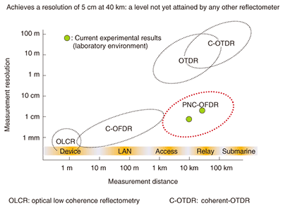
This finding suggests that plasma propagation might be suppressed upon reaching air holes. To test this idea, a fiber fuse was propagated in HAF having a structure in which Dmelted and c were nearly equal. The manner in which the core was destroyed was found to differ greatly from that in ordinary SMF. In SMF, cavities caused by core melting appeared sequentially at very short intervals (10 µm) while in HAF, cavities opened up at relatively long intervals (330 µm) and destroyed the core. When the section of destroyed core was analyzed, it was found that Dmelted broadened gradually and came to a stop near to the air holes. It was also observed that energy concentrated after propagation stopped and that a fiber fuse reoccurred, producing a repeating propagation phenomenon. Although the reason for this could be inferred to be the occurrence of boundary phenomena, a detailed explanation has not yet been given. 2.4 Phase-noise-compensated optical frequency domain reflectometry (Media & Equipment Monitoring Group )Coherent optical frequency domain reflectometry (C-OFDR) is a technique for locating fault points and making distortion-distribution measurements in the longitudinal direction of optical fiber. This technique has superior resolution characteristics but is limited to measurement distances of 2–3 km owing to the influence of phase noise from the light source. On the other hand, optical time-domain reflectometry (OTDR), which makes measurements within an optical fiber by injecting optical pulses to minimize the effect of phase noise, is capable of long-distance measurements but suffers from low resolution. Phase-noise-compensated OFDR (PNC-OFDR) achieves both long-distance and high-resolution measurements by monitoring phase noise with an auxiliary interferometer and removing its effect. It can therefore maintain accuracy even at long distances (Fig. 3). The auxiliary interferometer compensates for phase components by electrically storing phase noise data in memory and superposing components. This technique does not suffer from measurement disablement due to excessive phase noise at long distances. PNC-OFDR can achieve a resolution of 5 cm from 40 km away, which exceeds those of all other reflectometry methods.
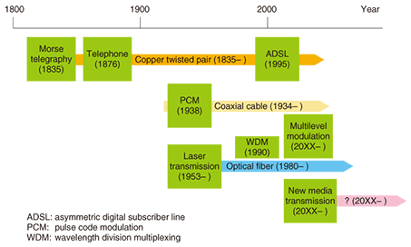
PNC-OFDR is very effective for detecting spans with high polarization mode dispersion (PMD). In optical fiber, PMD, which arises from optical birefringence, is one factor limiting transmission speed. It has come to be controlled in recent optical-fiber products but not in older products. To maintain transmission quality in the system, high-PMD spans must be located and replaced with new optical fiber. In a high-PMD span, short-period fluctuations in polarization occur in the transmission direction, and such fluctuations can be used to identify high-PMD locations. However, the fluctuation period is less than a few tens of centimeters, which means that detection requires a high resolution of 5–10 cm. Moreover, as the relay interval on transmission paths can currently be up to 80 km, a measurement-distance performance of at least 40 km is needed when making measurements from both ends of the interval. In an experiment to assess PNC-OFDR-based measurement, a high-PMD fiber taken from the field was installed at the end of about 40 km of SMF and PMD was clearly identified at that location. 3. Directions of future optical fiber research3.1 OverviewThe history of wired transmission media began with copper twisted pairs in Morse telegraphy and progressed to coaxial cable and then optical fiber in the 20th century, resulting in the development of new transmission systems (Fig. 4). The development of optical-fiber technology brought a huge leap in transmission capacity, but as demand for even higher capacities grew, capacity limits for conventional SMF began to be observed. Improved or new forms of transmission media are being eagerly sought. Two optical-fiber-based candidates for improved transmission media are multicore optical fiber and multimode optical fiber. The former has multiple cores within one clad, which can improve the spatial density and achieve high-capacity transmission. The latter has a structure capable of multiple-input multiple-output (MIMO) transmission and can achieve high-capacity transmission through multichannel propagation. Next-generation studies on the possibility of achieving transmission media for carrying terahertz-band and ultraviolet light signals are also being performed.
3.2 Higher cable densitySmall-diameter high-density optical cable technology increases transmission capacity by increasing cable density. A 1000-core optical fiber cable of the latest slot-type design in current use has an outer diameter of 23 mm and a weight of 0.45 kg/m, while the new small-diameter high-density optical cable currently under development is designed to have an outer diameter of 15.8 mm and a weight of 0.19 kg/m. Thus, the new cables will lead to very compact installations. A number of foreign firms are involved in making cables thinner and lighter and the most advanced research product from these firms has a density more than 1.5 times existing levels. Nevertheless, the pursuit of higher fiber densities is approaching inherent limits and we can expect the objective of future cable R&D to shift toward functional enhancements. 3.3 Manpower shortage solutionsThe number of employees involved in cable deployment and maintenance is forecast to decrease by around 60% in seven years time as aging workers retire. Replacing those employees with younger staff is one countermeasure, but there will still be a great shortage of staff with the appropriate skill set. There is therefore an urgent need for navigation-based support systems and equipment that can be operated by unskilled staff. ProfileCareer highlightsSenior Research Engineer, Executive Manager of the Access Media Project, NTT Access Network Service Systems Laboratories. Shigeru Tomita received the B.S. and D.Eng. degrees from Nihon University, Tokyo, in 1983 and 1993, respectively. After joining the Ibaraki Electrical Communication Laboratories of Nippon Telegraph and Telephone Public Corporation (now NTT) in 1983, he engaged in research on optical fibers and optical fiber cables. From 1995 to 1996, he engaged in development of outside plant planning tools in NTT’s Outside Plant Planning Division. After returning to the laboratories, he worked to develop optical components such as connectors and cords for use indoors. From 2008 to 2010, he was the leader of the Advanced Media Research Group. He is a member of IEEE and the Institute of Electronics, Information and Communication Engineers. |
||