 |
|||
|
|
|||
|
Feature Articles on Technical Solutions to Real-world Problems Vol. 9, No. 7, pp. 17–19, July 2011. https://doi.org/10.53829/ntr201107fa4 Corrosion Diagnosis Equipment for Inspecting Suspension CablesAbstractNTT has developed equipment for diagnosing corrosion in aerial suspension cables as an inspection tool. Although suspension cables use corrosion-resistant strands of steel wire having high anti-corrosion properties, cables in coastal areas can still suffer from localized corrosion inside the nozzle section of a terminal box. This diagnostic equipment can analyze such hidden corrosion nondestructively.
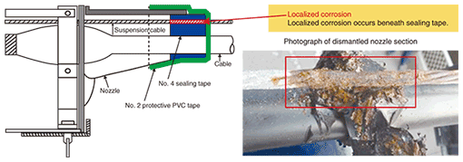
1. IntroductionAerial metallic cables and optical fiber cables are supported by a steel suspension cable running between utility poles. Modern suspension cables are made of highly corrosion-resistant strands of steel wire having both high anti-corrosion and anti-fatigue properties. In coastal areas, however, localized corrosion can still occur under the sealing tape in the nozzle section of a terminal box, as shown in Fig. 1. Such localized corrosion may often exist despite the absence of corrosion on the outside of the nozzle section, so a conventional visual inspection will fail to detect any corrosion at all. For a full inspection, it is therefore necessary to dismantle the nozzle, so the inspection is long and costly. NTT therefore felt the need for equipment that could diagnose suspension-cable corrosion inside the nozzle section nondestructively.
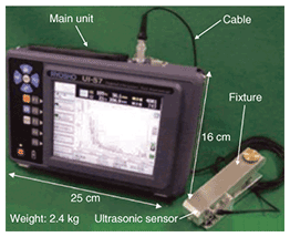
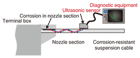
2. Inspection toolThe diagnostic equipment consists of a main unit, ultrasonic sensor, fixture, and cable (Fig. 2). Ultrasonic pulses are transmitted inside the suspension cable from the ultrasonic sensor, as shown in Fig. 3. At local corrosion sites, the ultrasonic waves are reflected back to the sensor, where they are detected. The waveforms of the reflected waves enable the presence and extent of corrosion to be determined.
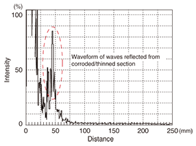
For better positioning accuracy and reproducibility of ultrasonic sensor results in corrosion inspections, the sensor is attached to the suspension cable using a fixture so that it emits ultrasonic waves into two wire strands at a time. Since the suspension cable consists of six outer wire strands surrounding a seventh central strand, the sensor must be put at three positions to inspect the six outer wire strands. In addition, one reference measurement is also performed to ensure that the surface conditions of the suspension cable do not affect the results, so a total of four measurements must be taken. A polymer sheet is inserted between the ultrasonic sensor and the suspension cable as a contact medium. Although it is common to use a gel such as glycerin with ultrasonic sensors, if the gel were to get among the cable strands, it could itself act as a source of corrosion, so for this reason and for better operability in the field, we decided to use a polymer sheet applicable to suspension cable diagnosis. An example of the waveform of waves reflected from a corroded section is shown in Fig. 4. This waveform is determined by the degree of corrosion and the distance of the corrosion site from the ultrasonic sensor. It is analyzed in the background on the diagnostic equipment and only the result of the corrosion level is displayed on the screen in an easy-to-understand manner.
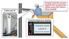
3. Inspection methodThe inspection method is shown in Fig. 5. A maintenance worker inspects a suspension cable from an aerial work platform positioned next to the terminal box. The inspection procedure is presented to the maintenance worker via figures and photographs displayed on the screen of the main unit one step at a time. Referring to these instructions, the maintenance worker attaches the ultrasonic sensor to the suspension cable using the fixture and proceeds to take measurements. If six wire strands are to be measured, for example, the instructions will use figures or images to show how the ultrasonic sensor should be slid along the suspension cable to measure three strand pairs. The worker will also be prompted to visually check for rust on the outside of the nozzle section emerging from the nozzle’s interior because corrosion progressing inside the nozzle section eventually appears as red rust outside the nozzle section. In short, the visual detection of rust is a sure sign of internal corrosion and evidence that the suspension cable needs renovation as soon as possible. Finally, the diagnostic equipment displays the diagnosis results. As shown in the example in Fig. 5, these results simply indicate the level of corrosion and the need for renovation.
4. ConclusionIt has been more than twenty years since corrosion-resistant suspension cables were first introduced, but because they are becoming increasingly used in coastal areas as well, we can expect the need for localized-corrosion inspections to grow. The suspension-cable corrosion diagnostic equipment can significantly reduce the inspection time and enable a large number of inspections of facilities by eliminating the need to dismantle nozzles of terminal boxes. As a result, effective maintenance becomes possible. |
|||


