|
|||||||||||||||||||
|
|
|||||||||||||||||||
       |
Regular Articles Vol. 9, No. 10, pp. 58–63, Oct. 2011. https://doi.org/10.53829/ntr201110ra1 Stripping-free Physical-contact ConnectorAbstractWe introduce a new physical-contact optical connector that uses a stripping-free connection method. The connector's assembly procedure does not require the coated optical fiber to be stripped or cleaved, which facilitates assembly. We designed the connector structure and the shape of the fiber's end to achieve physical-contact connection and developed a method for forming the required fiber endface. 
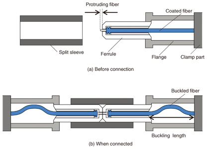
1. IntroductionOptical fiber is being widely introduced as a communication medium to handle the expansion of broadband services, and many ways of connecting optical fiber such as fusion splicing, mechanical splicing, and optical connectors have been developed and are being used in FTTH (fiber-to-the-home) systems. Conventional connection methods achieve good optical performance by aligning bare glass fibers after their coatings have been removed. All of these connection methods require careful handling of the bare glass fiber, which is fragile. This has led to demand for a method of connecting coated fibers that does not require a stripping process. Such a stripping-free fiber connection method would also enable us to simplify the assembly procedure. However, the concentricity error between the core and coating diameter of the coated fiber causes a large misalignment between the mated fiber cores. In this article, we introduce a new stripping-free optical connector that enables us to achieve a physical-contact (PC) connection and facilitate assembly. We also present experimental results for PC connection with a low connection loss. 2. Principle of stripping-free PC connectorA cross-sectional view of the new connector is shown in Fig. 1. This connector has a ferrule and a split sleeve to make it compatible with the existing SC [1] and MU [2] connectors. To achieve a PC connection, axial compression force is required between the mated fiber endfaces. We used the axial compression force generated by a buckled fiber to simplify the connector structure. As shown in Fig. 1(a), the fiber end protrudes from the ferrule end and the fiber is fixed to the clamp part. This structure enables us to buckle the fiber inside the flange when we connect the ferrules, as shown in Fig. 1(b). The buckling force can be controlled by setting the length of the buckled section of fiber (buckling length) [3].
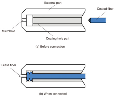
We designed the coated fiber alignment structure to achieve a low connection loss. The conventional ferrule is designed so that the glass fiber is inserted only after its coating has been stripped off. Therefore, we designed a new ferrule for the new stripping-free connector, as shown in Fig. 2. It consists of an external part with a microhole to align the glass fiber and a coating-hole part to align the coated fiber, as shown in Fig. 2(a). The external part has the same outer diameter as the conventional ferrule. When the coated fiber is inserted into the ferrule, the fiber end reaches the microhole located at the ferrule end through the coating-hole. When the fiber is pushed into the microhole, the fiber coating is pushed back slightly at the microhole’s entrance and only the glass enters the microhole, as shown in Fig. 2(b). The new connector enables us to obtain the same low connection loss as a conventional connector.
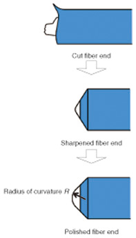
3. Fiber endface forming techniqueWe devised a new technique for forming the required fiber endface. This technique does not require the cleaver, which is a special tool, used in the conventional fiber preparation technique. The coated fiber is cut with an ordinary tool such as wire cutters. The new technique forms this cut fiber endface into a curved polished endface that enables us to achieve a PC connection, as shown in Fig. 3. It comprises a sharpening process and a polishing process. The sharpening process is designed to eliminate the cracked fiber end produced by the blade of the wire cutters when the coated fiber is cut. The polishing process is designed to create a curved fiber endface for PC connection.
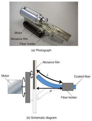
A photograph and schematic diagram of the endface forming tool for the sharpening and polishing processes are shown in Fig. 4. The tool consists mainly of an abrasive film, motor, and fiber holder. The fiber is held mechanically in the fiber holder. When the fiber is moved toward the abrasive film, the fiber end makes contact with the film and is pressed against it by the buckling force of the bent fiber. The motor rotates the abrasive film, which polishes the fiber endface.
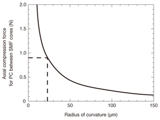
4. Fiber endface designWe designed the fiber endface shape for PC connection in order to determine the process conditions required for fiber endface forming. We calculated the axial compression force Fp needed to achieve PC connection with single-mode fibers (SMFs) with a curved endface. Fp is expressed as a function of the radius of curvature of the fiber endface R [4] by  where a is the core radius, E is the Young’s modulus, and n is the Poisson’s ratio of the fiber. The calculated results are shown in Fig. 5. The required Fp value increases as R decreases. Applying our previous findings that the estimated maximum axial compression force obtainable with a buckled fiber is 0.9 N [5], we determined from Fig. 5 that an axial compression force of less than 0.9 N requires a fiber endface with a radius of curvature of more than 23 μm.
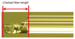
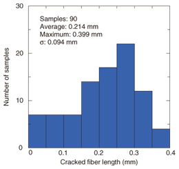
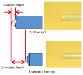
5. Processing conditions for forming coated fiber endfaceFirst, the end shape of a fiber cut with wire cutters was estimated. When a coated fiber is cut with wire cutters, the fiber end is cracked by the cutter’s blades. A photograph of the fiber end after we cut the coated fiber and removed the coating to measure the cracked length accurately is shown in Fig. 6. We measured the cracked lengths of the cut ends of 90 fibers after we cut the coated fibers with wire cutters (Fig. 7). The average cracked length was 0.214 mm with a standard deviation s of 0.094 mm. From this result, we estimated that the maximum cracked length likely to occur in practice is about 0.5 mm (average + 3s). The sharpening process eliminates the cracked end by reducing the fiber length, as shown in Fig. 8. Therefore, we designed the sharpening process to shorten the fiber by more than 0.5 mm in order to ensure that the formed fiber endface is not cracked.
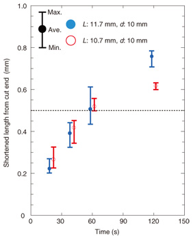
In the sharpening process, the shortened length of the coated fiber is determined by the processing time, the grain size of the abrasive film, and the shape of the bent fiber (bending shape). The bending shape is determined by the length of the fiber protruding from the fiber holder L and the distance between the abrasive film and the fiber holder d, as shown in Fig. 4. We measured the relationship between the shortened length of the coated fiber and the processing conditions when the forming tool was used. Here, the processing time and bending shape were varied. The abrasive film’s grain size was 40 μm. The distance between the abrasive film and fiber holder was 10 mm. The experimental results that we obtained for the shortened length of coated fiber are shown in Fig. 9. The shortened length increased with increasing processing time and L value. The results indicate that we can achieve a shortened length of more than 0.5 mm by controlling the bending shape and processing time.
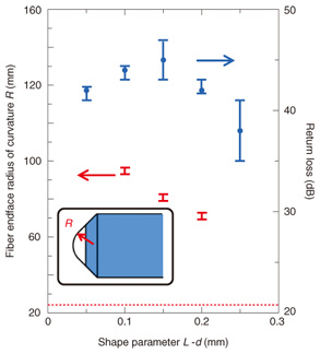
The sharpened endface is polished by using the forming tool, as shown in Fig. 4. The polished endface is formed by using the same configuration as in the sharpening process simply by changing the distance between the abrasive film and fiber holder. In the polishing process, L is smaller than in the sharpening process. A slightly bent fiber enables us to form the sharpened endface into a convex endface. We measured the relationship between the fiber’s bending shape and the radius of curvature of the convex endface when we changed the bending shape. An abrasive film with a grain size of less than 1 μm was used. The distance between the abrasive film and fiber holder was 10 mm. Our experimental results for the radius of curvature of the polished endface are shown in Fig. 10. They reveal that we can achieve the target radius of curvature of more than 23 μm by controlling the bending shape. We measured the return loss when we connected the polished endface using the axial compression force, as shown in Fig. 10. We found that the polished endface achieved PC connection with a return loss of more than 40 dB when we used a shape parameter L − d of less than 0.2.
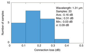
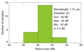
6. Optical performanceWe prepared a connector having a 100-μm-long microhole and a flange with a buckling length of 8 mm according to the PC connection design. We measured the optical performance of SMFs with endfaces formed with the forming tool. We confirmed that when the coated fiber was inserted into the microhole, the coating was pushed back and only the glass entered the microhole in accordance with design shown in Figs. 1 and 2. Histograms of the connection and return losses for 20 pairs of connected fibers are shown in Figs. 11 and 12, respectively. The connection losses for SMFs were less than 0.31 dB with an average value of 0.16 dB and standard deviation s of 0.09 dB. The minimum return loss was 42 dB, which confirms that all the connected fibers achieved PC connections. The results meet the performance requirements stipulated in IEC 61753-2-1, which sets the performance standard for SMF connection for an uncontrolled environment.
7. ConclusionsWe introduced a new physical-contact (PC) optical connector that does not require a coated fiber to be stripped and cleaved, so it facilitates connector assembly. A new method of forming the fiber endface enables us to achieve PC connection. In laboratory experiments, the stripping-free connector has achieved PC connection with a return loss of more than 42 dB and average connection loss of 0.16 dB. References
|
||||||||||||||||||