|
|||||||||
|
|
|||||||||
       |
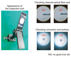
Practical Field Information about Telecommunication Technologies Vol. 10, No. 8, pp. 47–50, Aug. 2012. https://doi.org/10.53829/ntr201208pf1 Simple Tool for Inspecting Cleaved Optical Fiber Ends and Optical Fiber Connector End SurfacesAbstractThis article introduces a tool for inspecting cleaved fiber ends and connector end surfaces. The tool's main components are a microscope, cell phone, and special holders for the fiber or connector being inspected. It does not require focal adjustment and it can be used to inspect and clearly distinguish whether a fiber has been cleaved correctly and whether there are any scratches or contamination on the connector end surfaces. This tool provides a simple and cost-effective way to inspect cleaved fiber ends and connector end surfaces in the field. It is the twelfth in a bimonthly series on the theme of practical field information about telecommunication technologies. This month's contribution is from the Access Engineering Group, Technical Assistance and Support Center, Maintenance and Service Operations Department, Network Business Headquarters.
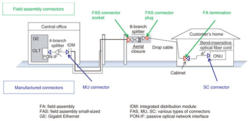
1. IntroductionIn recent years, broadband services delivered via fiber to the home (FTTH) have expanded rapidly and optical facilities are being constructed in vast numbers. As a result, the need to reduce capital expenditure and achieve efficient operation of a large number of optical facilities has increased. The importance of maintenance and management has also increased, and reducing operating expenditure has become a major issue. An effective way to reduce operating expenditure is to reduce facility faults. At the Technical Assistance and Support Center, we have targeted faults of the optical connectors used to connect optical fibers for detailed investigation and study. In this article, we describe the functions of a support tool that allows simple on-site inspection to evaluate the quality of connection work in order to reduce the number of optical connector faults. 2. Development backgroundA typical configuration of facilities for providing FTTH is illustrated in Fig. 1. From the optical line terminal (OLT) located in the central office, underground cables and aerial cables transmit signals to optical network units (ONU) located in customers’ homes. That configuration requires many connection points. Optical connectors are used in the central office, outdoors, and in customers’ homes. For each connection point, either a connector produced in a factory (manufactured connector) or a connector assembled in the field (field assembly connector [1]) is chosen and used as appropriate.
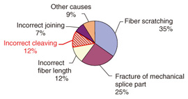
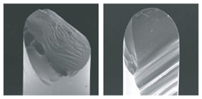
2.1 Faults of field assembly connectorsIn our investigation of fault causes, we collected actual defective field assembly connectors from an area of Japan and checked their optical characteristics and dismantled them to identify the cause of the fault [2] (Fig. 2). 12% of the faults were caused by increased optical loss due to incorrect cleaving of the optical fiber. An incorrectly cleaved fiber end is shown in Fig. 3.
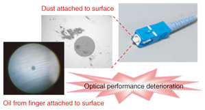
2.2 Faults of manufactured connectorsInvestigating the causes of faults of manufactured connectors, we found that contamination of the connector end surface by dust or finger oil or damage from scratching deteriorated the optical performance and resulted in a fault (Fig. 4).
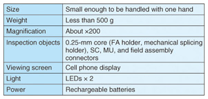
3. Overview of new toolIn order to reduce the two types of faults described above, it is effective to inspect optical fiber ends during field assembly procedures and during connection procedures. However, such work is usually performed outdoors and often in aerial closures high off the ground. At present, there is no suitable equipment for inspecting cleaved fiber ends and connector end surfaces at such work sites, so we developed a new, simple inspection tool for that purpose. 3.1 Design specificationsThe design specifications of the tool are listed in Table 1. The tool should be small enough to be handled with one hand and weigh less than 500 g. Its built-in microscope should provide magnification of about ×200. It is designed to inspect the cleaved ends of optical fibers attached to field assembly holders (FA holders) and mechanical splicing holders and the end surfaces of SC, MU, FA, and FAS connectors. A cell phone display should serve as the observation screen (direct visual inspection should also be possible). The tool should be equipped with light emitting diodes (LEDs) powered by rechargeable batteries to enable inspection in dark environments.
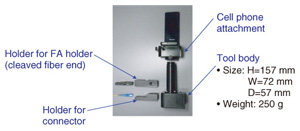
3.2 Configuration and structureThe configuration of the inspection tool is shown in Fig. 5. For low cost and high generality, the tool is composed of three main parts: a body that includes a microscope, a cell phone and its attachment, and special holders for cleaved fiber ends or connector end surfaces. The tool body is 157 mm high, 72 mm wide, and 57 mm deep and its weight is 250 g, so it is easy to use with one hand.
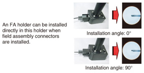
The holder for cleaved fiber ends is used to install the FA holder used in field assembly procedures. It can be used to check the cleaved optical fiber ends from four directions (0°, 90°, 180°, and 270°), so incorrect cleaving can be easily identified (Fig. 6).
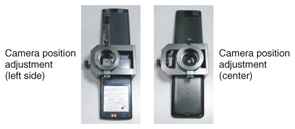
The cell phone attachment has a horizontal adjustment slide that we developed to cope with different types of cell phones having cameras in different locations. It ensures that the cell phone’s camera lens can be aligned with the tool’s microscope regardless of the type of cell phone being used (Fig. 7).
4. Evaluation resultsThe developed inspection tool and the results of checking cleaved optical fiber ends and connector end surfaces with the cell phone display are shown in Fig. 8. We can clearly see whether there are any defects in the cleaved fiber ends or any contamination on the connector end surfaces, confirming that it is possible to check the quality of the work visually.
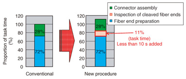
Evaluation of the time required for the inspection of the cleaved fiber ends revealed that preparing the optical fiber end accounted for 72% of the task time and assembling the connector accounted for 28% of the time before the introduction of the cleaved-fiber-ends inspection. Adding the cleaved-fiber-ends inspection task extended the time by 10 s, taking 11% of the entire work time. This result confirms the workability of the inspection (Fig. 9).
5. ConclusionThe tool for inspecting cleaved optical fiber ends and connector end surfaces developed by the Technical Assistance and Support Center has good visual clarity and ease of use with good performance for field inspection of cleaved optical fiber ends and connector end surfaces. As the number of FTTH subscribers increases in the future, we can expect an increase in the use of optical connectors. Therefore, reducing connector faults will be an urgent goal, and we believe that this tool will be an effective measure for that purpose. We will continue to develop various kinds of products and support tools to contribute to efforts to reduce faults in the access network even further. References
|
||||||||