|
|||||||||||||||
|
|
|||||||||||||||
       |
Regular Articles Vol. 11, No. 1, pp. 44–49, Jan. 2013. https://doi.org/10.53829/ntr201301ra2 Evaluation of Earthquake Resistance of Shield-tunnel/vertical-shaft Connections and Countermeasure TechnologyAbstractThis article describes a technique developed by NTT for assessing the need for earthquake-proofing measures in shield tunnels and introduces technology for effective and economical seismic-motion countermeasures.
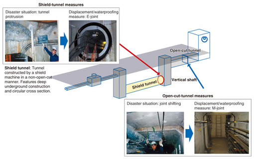
1. IntroductionIn the aftermath of the Great Hanshin-Awaji (Kobe) Earthquake of 1995, NTT implemented earthquake-proofing measures for its tunnel facilities consisting of open-cut tunnels and shield tunnels (Fig. 1).
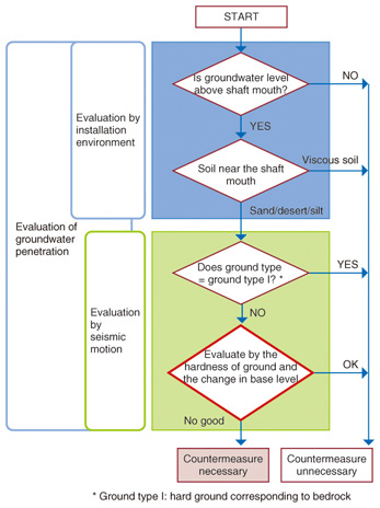
In the open-cut tunnels, ground liquefaction caused by the earthquake caused the tunnel section connecting an NTT building or vertical shaft to shift or uplift. To counteract such phenomena, we developed a rubber-based, flexible joint as an earthquake-proofing measure in 1996 and proceeded to implement it. The earthquake also caused some minor damage to shield tunnels, for example, cracks and water leakage in the tunnel section connecting to a vertical shaft, and in some cases, caused that section to protrude into the shaft (Fig. 1). However, if such damage were to occur under high-water-pressure conditions, the shaft might flood, which, in turn, could affect communication services and prevent safe working conditions from being ensured during restoration work. In light of these concerns, NTT developed technologies to counter earthquake-induced ground movement (seismic-motion countermeasure technologies) in 2002 [1]. Issues arose, however, in the implementation of those technologies, such as the lack of criteria for applying such countermeasure technologies and insufficient working space within the tunnels. As a result, earthquake-proofing measures for shield tunnels in sections connected to a vertical shaft have not sufficiently progressed. A major inland earthquake in the Tokyo metropolitan area and major earthquakes in the Tokai, Tonankai, and Nankai regions of Japan are expected to occur sometime in the future. The reliability of shield tunnels, which are considered to be critical facilities in the network, must therefore be ensured. To this end, we have been studying a method for evaluating the necessity of earthquake-proofing measures and have been working on effective seismic-motion countermeasures since 2009. 2. Method for evaluating the necessity of earthquake-proofing measuresOur method for evaluating the earthquake-resistance of the connecting section of a shield tunnel consists of judging whether earthquake-proofing measures are needed to prevent an inundation of water into the tunnel. Specifically, we judge whether groundwater will penetrate the tunnel by first performing an evaluation based on the installation environment of the shield tunnel and then performing one based on seismic motion. In the former, we determine whether the position of the shaft mouth is above the groundwater level and whether the soil in the vicinity of the shaft mouth is of a type that is easily penetrated by water. In the latter, we determine whether the ground in the vicinity of the shaft mouth is of a type targeted for earthquake-proofing measures and finally investigate whether groundwater will penetrate it on the basis of a characteristic value of the ground in the vicinity of the shaft mouth. We have prepared a decision flowchart to facilitate this evaluation procedure (Fig. 2).
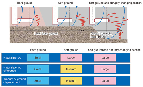
The characteristic value of the ground based on seismic motion refers to the ground’s natural period as an indicator of its hardness. It is known to have a correlation with ground displacement. In addition, the difference in natural period between two points in subsurface ground*1 can be used as an index of bedrock*2 change. The value of this difference and the relative ground displacement would tend to be large for an abruptly changing section of bedrock. This analysis of ground behavior based on seismic motion has been clarified by applying the finite element method (FEM)*3 (Fig. 3).
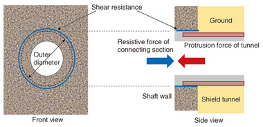
The most accurate method for evaluating earthquake resistance would be to perform FEM analysis on each and every tunnel, but this would require a high degree of expertise and much labor and expense. A technique that a non-specialist could easily use to evaluate the necessity of earthquake-proofing measures was therefore required. We consequently proposed a technique for determining the likelihood of shield-tunnel protrusion from the relationship between the driving force of shield-tunnel protrusion into the vertical shaft and the resistive force at the mouth of the vertical shaft [2] (Fig. 4). After formulating the effects of relative ground displacement based on the ground’s natural period and natural-period difference and comparing them with the results of ground analysis by FEM, we were able to improve reliability by taking the following three items into consideration: (1) dynamic effects, (2) effects in the depth direction, and (3) the drop in rigidity of ground affected by seismic motion.
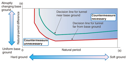
We also prepared a graphic chart to make it easier for users to apply the technique when determining whether earthquake-proofing measures are needed (Fig. 5).This decision chart aids the user in judging the necessity of an earthquake-proofing measure on the basis of the ground’s natural period and natural-period difference. Furthermore, since the results of ground analysis by FEM indicate that the distance between the shield tunnel and bedrock can affect this decision, this chart includes two lines separating the necessary and unnecessary regions. These two lines show that the natural period and the natural-period difference of the ground in question become larger as the distance between the tunnel and bedrock increases; consequently, the region in which countermeasures are deemed necessary becomes larger. Additionally, ground-related information such as hardness, soil type, and depths of various soil layers can be obtained from boring data if such data are available. Such information can be used to manually calculate the natural period and natural-period difference, thereby making it relatively easy to judge the need for earthquake-proofing. This decision chart has been found to be valid by comparing its predictions with actual examples of damage caused by the Great Hanshin-Awaji (Kobe) Earthquake and the Great East Japan Earthquake.
A key feature of this decision technique is a decision flowchart that provides a simple procedure for judging the need for earthquake-proofing in the field. In this way, sites requiring earthquake-proofing measures can be narrowed down and examined in detail. This makes for more efficient collection and use of boring data to compute the natural period and natural-period difference that are used with the decision chart to make a final decision. This decision chart focuses on the hardness of the surrounding ground and sudden changes in the nature of that ground. Comparisons of the results produced using the chart with those of FEM-based ground analysis have shown it to be a reliable means of evaluating the need for earthquake-proofing. Moreover, it requires less specialized knowledge, labor, and expense than the application of FEM analysis to each and every shield tunnel. It is also easy to apply in the field if boring data are available, which makes it an advanced technique that cannot be found in other lifeline infrastructure design policies.
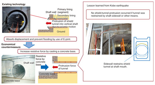
3. Economical countermeasure technologyThe existing countermeasure involves installing a rubber joint where the shield tunnel connects with the vertical shaft to accommodate any protrusion of the shield tunnel due to seismic motion and to prevent water from penetrating the tunnel. However, the presence of obstacles in addition to the expense of construction work can make it difficult to install a rubber joint and consequently to apply this method. Surveys on actual damage in shield tunnels caused by the Great Hanshin-Awaji (Kobe) Earthquake revealed that no tunnel protrusion occurred if the tunnel was restrained by the sidewall of the vertical shaft. We used the results of these surveys to devise a method for preventing the protrusion of a shield tunnel by casting a concrete base to increase the resistive force [3]. This significantly reduces the cost of construction when implementing countermeasures and can be applied even if obstacles are present in the area (Fig. 6).
4. Future plansWe plan to prepare operation manuals and conduct briefings in order to promote the implementation of this technology in actual operations. References
|
||||||||||||||