|
|||||||||
|
|
|||||||||
       |
Regular Articles Vol. 11, No. 7, pp. 42–47, July 2013. https://doi.org/10.53829/ntr201307ra2 Distributed Array Antenna Technique for Satellite CommunicationsAbstractNTT Access Network Service Systems Laboratories has developed a distributed array antenna (DAA) technique to achieve a higher gain earth station antenna for satellite communications. The DAA configuration comprises several smaller antennas and has an antenna gain equivalent to that of a conventional large-aperture antenna. We applied the configuration to two antennas and experimentally confirmed that the DAA achieves increased antenna gain.
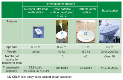
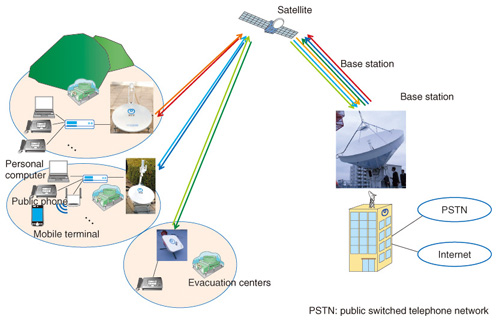
1. IntroductionSatellite communication systems are utilized to provide temporary communication lines when a disaster occurs. An example is the system established by the NTT Group that uses the Ku-band (14 GHz/12 GHz) for communications to provide relief in the early stages of post-disaster recovery. Many different types of earth stations are used for disaster recovery, such as those shown in Fig. 1 [1], [2]. Terminal earth stations are deployed at evacuation centers, and the base station aggregates the communication lines from these terminal earth stations, as shown in Fig. 2.
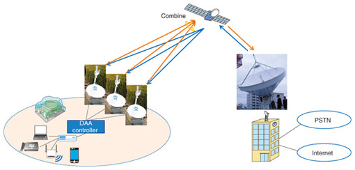
In stricken areas in particular, the earth stations need to make use of small-aperture antennas that can be transported easily. One problem with these stations is that the maximum number of available telephone lines and the maximum transmission bit rate are limited because the antenna gain is proportional to the antenna aperture. However, large-aperture antennas are heavy to transport and must be installed by a skilled engineer. A further problem is that the base station has a very large and heavy aperture antenna in order to obtain high antenna gain. A certain amount of space is required on building rooftops for this kind of antenna, and such space is also limited. Therefore, the base station antenna should consist of relatively small and light antennas that can be easily placed. 2. Proposed configurationTo address these problems, NTT Access Network Service Systems Laboratories proposes a distributed array antenna (DAA) technique and configuration, shown in Fig. 3. The DAA configuration, which comprises several smaller antennas, has an antenna gain equivalent to that of a conventional larger aperture antenna. If we apply this DAA configuration to three 0.75-m-diameter antennas (Fig. 1), we can achieve gain almost equal to that of a 1.2-m-diameter antenna. Furthermore, the base station can achieve the antenna gain of a 4.5-m-diameter antenna that has a configuration of four 2.4-m-diameter antennas. The total weight of these antennas is 1200 kg, which makes it smaller and lighter than a conventional base station antenna. Thus, there is greater flexibility in positioning it because it requires less installation space. Another benefit is that the use of multiple antennas improves failure resistance; if one antenna fails, the others can maintain the communication even with a lower bitrate.
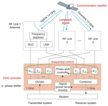
3. Key techniqueThe DAA system consists of a modem, several radio frequency (RF) units, and a DAA controller, as shown in Fig. 4. Each RF unit includes an antenna, a frequency duplexer, a block upconverter (BUC), and a low noise block converter (LNB). The BUC converts the carrier frequency from the modem (1 GHz) to the transmission frequency band (14 GHz) and amplifies the transmitted signal level for the uplink. The satellite relays these signals while converting the frequency from the 14-GHz band to the 12-GHz band, and the LNB amplifies the received signals and converts the frequency from the received frequency band (12 GHz) to the modem (1 GHz).
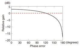
To obtain a higher antenna gain, it is essential to maintain in-phase combining at the satellite onboard antenna in the DAA uplink. The modem output signal is first divided by a divider. Then, the phase of the signal is calibrated by a phase shifter, and the signal is supplied to the antennas. If a phase error occurs between the signals transmitted by the RF units, it will degrade the composite antenna gain, as shown in Fig. 5.
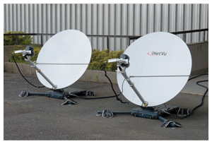
There are two possible causes of phase errors in the DAA uplink: the location of the RF unit and slow fluctuation of BUC characteristics over time. Generally, the conventional configuration has a feedback circuit to compensate for these phase errors [3]. However, the proposed DAA does not require a feedback circuit. The DAA compensates for this by having stations transmit their own signals to the satellite and then receive them back from the satellite. During that time, the phase shifters calibrate the phase to maintain the loopback signal at a maximum level. The two kinds of phase errors can be calibrated comprehensively because the phase error caused by the RF unit location consists of static phase offset, and the phase error caused by BUC fluctuation is slower than the satellite delay (250 ms). Specifically, the phase calibration is carried out by selecting phase shifters one-by-one. The selected phase shifter shifts phases at a constant positive or negative value. Simultaneously, the loopback signal level is registered by a monitor. Then, the DAA controller chooses the set phase that records the highest signal level. The features of the proposed system are: - No feedback signal generator for transmitted signals is required. - There is no need to remodel the RF units or modem because a controller is inserted between a general purpose modem and the RF units. - The two abovementioned causes of phase errors can be compensated as a whole. In the downlink, the DAA controller combines the signals from each RF unit so as to maximize the combined received signal level. There are also two possible causes of phase errors in the downlink: RF unit location and slow fluctuation of LNB characteristics with time. These phase errors can be compensated for in a similar manner. 4. Satellite experimentsWe configured the DAA using two commercially available RF units in 1.2-m-diameter antennas, shown in Fig. 6, and we used the Ku-band satellite service to evaluate the phase calibration method, antenna gain, and transmission characteristics of the signal constellation and the bit error rate (BER) performance.
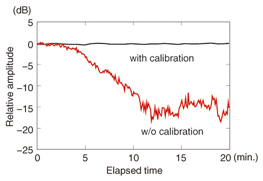
We conducted a test to evaluate the phase calibration method. The loopback signal level results with and without calibration are shown in Fig. 7. For the test without calibration, the calibration was turned off at elapsed time 0. We can confirm from the results that the received signal level is degraded. By contrast, with our calibration method the signal level is kept constant.
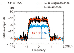
With the DAA, the gain is twice as high as that of the 1.2-m-diameter antenna, and the BUC output power is also twice as high, theoretically a fourfold (6 dB) improvement. To evaluate the DAA gain, we compared the received signal spectra of the DAA, a 1.2-m-diameter antenna, and a 1.8-m-diameter antenna (Fig. 8). The 1.8-m-diameter antenna had twice the gain of the 1.2-m-diameter antenna. To establish equal conditions, we used a 1.8-m-diameter antenna that had a BUC whose output power was twice as high as that of the BUC in the smaller antenna. The results show that the received signal spectrum of the DAA is almost the same as that of the 1.8-m-diameter antenna and is 5.9 dB higher than that of the 1.2-m-diameter antenna. These results indicate that the degradation from the theoretical value is only 0.1 dB.
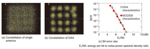
Finally, we evaluated the transmission characteristics of 3.2-Mbit/s, 16-quadrature amplitude modulation (QAM) signals. The 16-QAM scheme has a 4×4 signal constellation, and if there is sufficient transmission energy, a constellation can be easily distinguished. The signal constellations for the 1.2-m-diameter antenna and the DAA are shown in Figs. 9(a) and (b), respectively. A 4×4 signal constellation was impossible to distinguish for the 1.2-m-diameter antenna because there was insufficient transmission energy. However, because of the increased gain in the DAA, the transmitted power was high enough to enable a 4×4 signal constellation to be distinguished. The measured BER performance is shown in Fig. 9(c). The resulting BER performance is close to that of the case using a direct cable connection (MODEM).
5. ConclusionsWe have developed a DAA technique that comprises several small-aperture antennas and that can achieve gain equivalent to that of a large-aperture antenna. The DAA controller can be easily introduced in existing satellite earth station antennas and modems to increase the antenna gain. Experimental results for Ku-band satellite communication confirmed that the DAA increased the gain. In the future we plan to enhance our system in order to extend its usability to areas such as maritime mobile communications. References
|
||||||||