|
|||||||||||||||||||||||
|
|
|||||||||||||||||||||||
       |
Regular Articles Vol. 11, No. 10, pp. 21–26, Oct. 2013. https://doi.org/10.53829/ntr201310ra1 Load Modulation Applied to Magnetic Resonance Wireless Power Transfer Technology and Its ApplicationsAbstractThe newly developed magnetic resonance wireless power transfer technology is being intensively researched since it is easier to use than conventional technology and has potential applications in various fields. In this article, we first provide an overview of similar techniques; then we introduce a method of using this power transfer technology that adopts load modulation in order to increase its range of applicability. We also describe an example of how this method can be used to reduce the effort needed for manhole maintenance, and we present evaluation results regarding the optimal placement of the transmitter and receiver coils in the example application. Keywords: wireless power transfer, magnetic resonance, load modulation
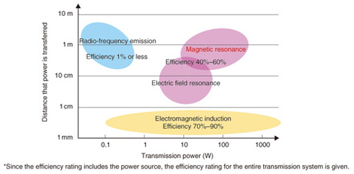
1. Introduction––magnetic resonance wireless power transferIn 2007, a new wireless power transfer technology was developed at the Massachusetts Institute of Technology (MIT) [1]. This technology is referred to as magnetic resonance*1 and differs from conventional wireless power transfer technologies such as radio frequency radiation and electromagnetic induction, as shown in Fig. 1 [2]. One example of radio frequency radiation technology is a solar power satellite (SPS)*2, where energy is changed from an electrical current to an electric wave and transmitted between antennas. This method is applied when transmission distances are comparatively long. By contrast, electromagnetic induction is used in, for example, chargers for electric toothbrushes and electric shavers. Another name for this technology is the non-contact method. As the name suggests, electrical power is transmitted when one of a pair of coils is brought into close proximity with the other coil. Current is passed through the transmitter coil, and magnetic flux is transmitted to the receiver coil where a current is induced. In 2010, Qi, an international inductive power standard (Ver. 1.0) for up to 5 W, was established, and devices based on this standard have since been commercialized [3]. In comparison to these conventional technologies, magnetic resonance has intermediate characteristics, as shown in Fig. 1. Furthermore, even if the direction or position of the opposite coil is not aligned perfectly, the degradation in the transmission efficiency is slight, and in this sense it is easy to use. Research and development on this technology is being actively pursued over a wide range of fields such as automotive, consumer electronics, and medical fields, and new applications are expected to be introduced.
The principle of magnetic resonance power transfer is often explained by using the example of two distant tuning forks, where when one is struck the other resonates and begins to generate sound. A more precise explanation is that the quality factors (Q factors) of the transmitter and receiver coils are increased, and by matching the resonant frequencies of both coils, the electromagnetic coupling between the coils is strengthened, and electrical power is transferred. This transmission principle is basically the same as that for the electromagnetic induction mentioned earlier. The transmission efficiency of both methods is given by the product of the coil Q factor and the coupling coefficient. The electromagnetic induction approach increases the coupling coefficient by bringing the coils into close proximity, and the magnetic resonance approach increases the coil resonance characteristics, i.e., the Q factor.
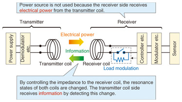
2. Adopting load modulationThe NTT Access Network Service Systems Laboratories is engaging in preparations for plans to further improve the utilization of various anticipated applications for magnetic resonance power transfer technology. One such application involves adopting load modulation [4]. Load modulation is a technology used in conducting communications. An example is passive radio frequency identification (RFID) tags, which are already widely used. A reader-writer transmits a carrier wave, and in response, the internal impedance in the RFID tag changes depending on the response data and generates a reflected wave, which is then received by the reader-writer. A schematic illustration of a magnetic resonance power transfer setup that adopts load modulation is shown in Fig. 2. In the figure, the receiver is connected to a sensor, and electrical power that is transmitted from the transmitter coil drives the receiver circuit and sensor. Conversely, on the receiver side, the load impedance inside the receiver changes depending on the sensor information, and the resonant state between the transmitter and receiver coils changes. This change manifests a change in the reflection characteristics of the transmitter coil input port, and through detection and demodulation, information is extracted as a signal. With this construction, the use of power sources such as commercial power supplies and batteries is unnecessary on the receiver side (maintenance-free). It is then possible for the receiver side to draw power off the power supplied to the sensor and obtain sensor information.
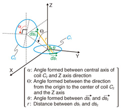
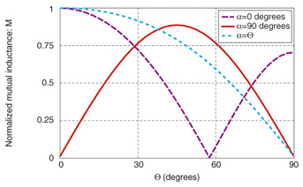
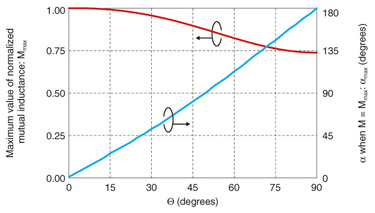
3. Coupling properties of arbitrarily set coils and application example of manhole maintenanceAs mentioned earlier, various applications of the magnetic resonance wireless power transfer technology are expected since it is easier to use than conventional power transfer technology. The transmitter and receiver coils do not need to be positioned facing each other and therefore, the transmission efficiency properties of an arbitrarily arranged coil configuration need to be ascertained. On the basis of coupling mode theory, we show the transmission efficiency of magnetic resonance wireless power transfer using performance index U in the following equation [1].  Here, Q1 and Q2 are the respective Q factors for coils C1 and C2, L1 and L2 are the respective self-inductance values for coils C1 and C2, and M is the mutual inductance between coils C1 and C2. From Eq. (1), if the Q factors of the coils and self-inductance are assumed to be fixed, the transmission efficiency representing the performance index U depends on mutual inductance M. The following equation expresses mutual inductance M when it is an ideal conductor based on Neumann’s formula (µ0: magnetic permeability in free space) On the basis of Eq. (2), using the loop coil pair in Fig. 3, we calculated the mutual inductance, which is plotted in Figs. 4 and 5. It is evident in Fig. 4 that the mutual conductance is high for the intermediate range of 45°–70° as the angular position of coil C2, Θ, when the angle of inclination of coil C2, α, is 90°. Furthermore, we can see in Fig. 5 that the maximum value of the mutual inductance, Mmax, does not change significantly (1 => 0.75) even if the angular position of coil C2, Θ, is changed; that αmax when M = Mmax depends on Θ; and that αmax changes over the range of 0–180°. Keeping in mind the above characteristics, we describe the maintenance of manholes as an application example of wireless power transfer adopting load modulation [5].
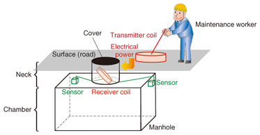
There are approximately 680,000 communications related manholes throughout the country. Among these, 80% have been in service for more than 30 years [6] and are deteriorating. Furthermore, inspecting the interiors of manholes requires much effort. Permission must be obtained in advance to access the road, and arrangements such as for traffic control and manhole ventilation must be made prior to inspection. Accordingly, studies have been done on optimizing the maintenance work using wireless technology [7], [8]. In this application example, a receiver coil and sensors used in structure diagnosis such as a strain gauge and accelerometer are installed inside the manhole. Load modulation is used to communicate the sensor information, and magnetic resonance power transfer technology is used to supply electricity to the sensors. This makes it possible to tackle the goal of reducing the amount of maintenance work in manholes and also that of strengthening the cost competitiveness and improving the reliability of the transmission equipment. Here, we investigate a specific configuration method for the receiver coil based on the mutual inductance characteristics in Eq. (2) for this type of application. The construction of a general manhole is classified into the cover, the chamber, and the neck that connects the chamber and surface (Fig. 6). In some cases, the chamber is constructed of concrete that contains a rebar grid; because the rebar can affect the magnetic resonance wireless power transfer, the receiver coil is placed in the neck. In contrast, the cover is made from cast iron, which has a large effect on this system. Therefore, the transmitter coil is positioned level to the ground on the periphery of the cover to avoid the upper part of the cover and to simplify the maintenance work.
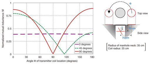
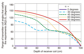
We calculated the mutual inductance based on the above conditions; the results are shown in Fig. 7. These results show that when the receiver coil is positioned in the neck at 90° (vertical), the range of the angle of the transmitter coil placement (angle at which the transmitter coil is installed) to achieve high mutual inductance is extremely wide. Next, we show the results when the required mutual inductance of the system is tentatively 0.5, and the range of angles of the transmitter coil location that exceeds this requirement is calculated from the depth of the receiver coil as a parameter (Fig. 8). From these results as well, for a practical receiver coil depth (a few tens of centimeters), when the receiver coil is installed in the neck at 90°, we find that the range of angles of the transmitter coil placement that satisfied the standard value (M ≥ 0.5) is extremely wide.
4. Future developmentIn this article, we summarized wireless power transfer technology and introduced the magnetic resonance method that has been extensively researched and developed in recent years. We also described the magnetic resonance method adopting load modulation, a method for improving applicability, and an application example. In terms of practical application, various problems exist such as achieving high efficiency of the coils themselves, achieving high efficiency of the entire system including the load system, and determining how to adjust and alleviate the reduction in efficiency due to variations in impedance caused by the influence from the surrounding environment. The Wireless Power Transfer Working Group of the Broadband Wireless Forum is actively discussing standardization with a focus on wireless power transfer including magnetic resonance, cooperation with other countries, and legislation and regulation related to radio laws and human safety. Over the past few years, extensive discussions and investigations have taken place from various viewpoints, and we anticipate that the day will be upon us soon when products and services employ this technology. References
|
||||||||||||||||||||||