|
|||||||||
|
|
|||||||||
       |
Feature Articles: R&D on Maintenance and Management Technologies for Telecommunication Infrastructure Vol. 12, No. 10, pp. 17–24, Oct. 2014. https://doi.org/10.53829/ntr201410fa3 Protecting Telecommunication Services from Earthquake DamageAbstractTo protect telecommunication network facilities from damage caused by major earthquakes, NTT Access Network Service Systems Laboratories has been continuously conducting research and development on technology to make the telecommunication infrastructure resistant to earthquakes and to improve the accuracy of evaluating earthquake resistance. This article describes our work to improve the technology for evaluating non-standard private bridges that was introduced in 2013 as a measure to improve the earthquake resistance of important facilities. It also describes the technology currently under development for evaluating the earthquake resistance of conduit. Keywords: earthquake resistance technology, private bridge, damage estimation technology
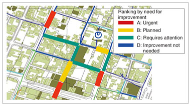
1. IntroductionThe 2011 Great East Japan Earthquake and Tsunami caused enormous damage to the telecommunication infrastructure. The government warns that we will remain susceptible to large-scale damage from earthquakes that originate in the Nankai Trough or directly beneath the Tokyo area well into the future. Therefore, the need to strengthen facilities to make them safer and more resistant to earthquakes is higher than ever. NTT Access Network Service Systems Laboratories is working to improve the reliability of telecommunication infrastructure facilities based on an analysis of damage to facilities caused by major earthquakes that occurred in the past. In particular, since the Great Hanshin Earthquake in 1995, the earthquake resistance of cable tunnels and standard private bridges, which are important infrastructure facilities, has been evaluated according to new criteria based on the definition of a Level 2 Earthquake by the Japan Society of Civil Engineers. In addition, measures to protect structures in the event of large-scale earthquakes have been applied. This article describes the evaluation technology introduced in 2013 for improving the reliability of earthquake resistance of non-standard private bridges (defined in section 2). Much importance has been placed on strengthening underground pipeline systems located in areas likely to experience ground liquefaction during earthquakes. Improvements such as making conduit joints flexible have been made, and the effectiveness of these measures was evident after the Great East Japan Earthquake in 2011 and other major earthquakes. However, these earthquake-resistant joints are applicable only for newly constructed facilities; they are not currently used to update conduit that was constructed and installed before the improvements were introduced. Therefore, technology has been developed for improving the earthquake resistance of old, standard conduit that is already installed without having to excavate it. The result of this development is the pipe insertion type (PIT) new conduit method, which has been confirmed to reduce damage from earthquake motion and ground deformation through the use of a free-standing lining [1]. Currently, technology for evaluating earthquake resistance is being studied in order to effectively apply renovation technology such as the PIT method to the huge quantity of existing standard conduit. We have adopted a macro-evaluation method (Fig. 1) to determine the degree of damage and the number of damage incidents that may occur in a wide area in the event of an earthquake. This method uses a statistical analysis of damage from past earthquakes based on the relationship of the earthquake magnitude, whether liquefaction occurred, the type of conduit pipe, and the age of the structure. For example, the damage rate is A% for a steel pipe constructed before 1985 that is exposed to an earthquake measured at upper 6 on the Japan Meteorological Agency seismic intensity scale with liquefaction. That method has been used to predict damage from a major earthquake that is expected to occur in the near future [2].
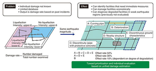
A problem with this method, however, is the difficulty in evaluating with precision individual sections of conduit in order to decide where to begin implementing measures to strengthen the huge number of old conduit pipes against large-scale earthquakes. Currently, we are aiming at developing technology for identifying the specific weak points of individual pieces of conduit (Fig. 2). Our specific objective is to achieve technology that will enable highly accurate damage prediction through quantitative evaluation of various factors that affect the underground environment, for example, loss of strength due to the deterioration of steel pipe, the line type, which refers to the characteristics of conduit such as whether it is horizontal curving or longitudinal sloping, or whether protective concrete is used, and the ground conditions where the conduit is located.
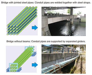
2. Earthquake resistance evaluation technology for non-standard private bridgesNTT has constructed and owns two types of private bridges that support telecommunication cables (telecommunication bridges): standard and non-standard. The standard bridges conform to current NTT standards. In contrast, the non-standard bridges are bridges that conform to old standards or that were devised and constructed individually according to on-site conditions. There are two broad types of non-standard private bridges (Fig. 3).
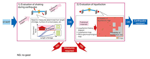
Standard private bridges have been evaluated for earthquake resistance; however, the structure of non-standard private bridges differs greatly from ordinary bridges, and hence, their behavior during an earthquake is not clear. Private bridges are laid across rivers and carry assorted cables used to provide telecommunication services. A failure in one of these bridges would affect third parties such as pedestrians, cars, or vessels traveling on or under the bridge. Although there have been no incidents of bridge failures in past earthquakes, adequate construction and maintenance techniques are necessary because these bridges are important facilities for ensuring network reliability and safety. For this reason, we have been investigating the conditions under which damage occurs and clarifying the damage mechanism during earthquakes by investigating the vibration characteristics and structural analyses of existing facilities [3]. The factors relevant to earthquake damage that may affect bridges fall into two broad types: (i) the inertial force from vibration caused by the earthquake and (ii) collapse of the bridge abutments or the main bridge structure due to liquefaction of the ground that supports the bridge. We have developed technology for understanding the effects of these factors using easily obtained data. The process used to evaluate earthquake resistance is illustrated in Fig. 4.
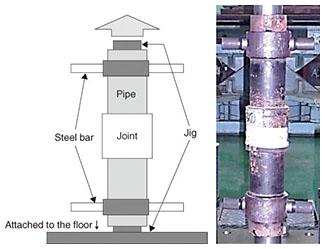
2.1 Evaluation of earthquake vibrationWe have clarified the vibration movement of non-standard private bridges by investigating actual non-standard bridges and analyzing the results. We then used the results to create a chart for comparing the inertial forces generated by earthquake motion to the resistance of the steel materials used in the bridges based on simple data such as the length of the bridge and the number of conduit pipes. For bridges without beams, which are one type of non-standard private bridge, we found that the possibility of damage can be determined from the length alone. 2.2 Evaluation of liquefactionNon-standard private bridges that do not have strong abutments are susceptible to collapse due to liquefaction of the surrounding ground. Therefore, such bridges that are located in areas where the risk of liquefaction is high are classified as requiring improvements. We also created a procedure for determining liquefaction areas using data published by local governments or research organizations. Previously, the determination of liquefaction was based on time-consuming studies that required the collection of geotechnical boring data in the vicinity of the facility. However, liquefaction can be determined by a procedure that effectively uses liquefaction history diagrams, liquefaction maps that record the value of the potential of liquefaction, micro-geomorphological maps, and other published data, thus making it possible to determine the risk of liquefaction for a particular area. These two evaluation processes enabled us to identify non-standard private bridges that are at high risk of damage and that consequently need immediate countermeasures. 3. Improving earthquake resistance evaluation technology3.1 Factoring in deterioration of underground conduitEstimating the damage to underground conduit during an earthquake was previously done assuming that the conduit was sound before the earthquake. Actually, however, a lot of conduit has been in place for over 30 years and may therefore be partially corroded in some areas, and corroded steel conduit is more likely to be weaker than sound conduit. To more accurately determine the location where damage may potentially occur, it is necessary to know the location of weakened conduit and also to what extent the performance of such conduit has decreased. For that purpose, we conducted performance tests on collected conduit pipes that were removed in construction work throughout the country (Fig. 5) to determine the degree of deterioration.
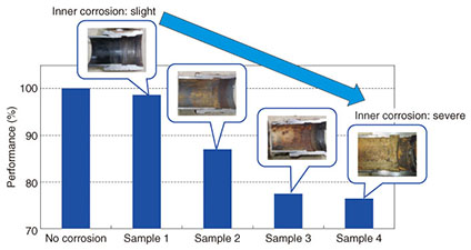
The results of the performance testing showed that, on average, the formerly buried conduit performed at roughly 90% of the level of sound conduit, which is to say that the average loss of strength was 10%. However, there was a large dispersion in the values for individual samples, and many samples performed as well as sound pipes. More detailed observations revealed that although there were some exceptions, the performance tended to decrease when there was severe corrosion on the inner surface (Fig. 6). We are currently at the stage of confirming the results qualitatively, but in the future, we plan to develop technology for predicting the decrease in performance of individual conduits by conducting more basic tests and on-site investigations to reveal the relation of loss of strength to the length of time the conduit has been underground and the ground environment of the conduit.
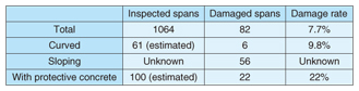
3.2 Factoring in the line type of underground conduitNTT underground conduit pipes follow the paths of roads and may deviate from a straight line vertically or horizontally to avoid other buried objects. External forces due to earthquakes may be concentrated at such deviations, making those locations weak points. Some conduit is buried at shallow depths, and the inner cable is protected from construction such as road excavation by concrete that is poured around the conduit. (Since 2003, a protective cover made from recycled optical fiber has been used instead of concrete.) In such locations, the conduit characteristics are discontinuous because the conduit is partially contained within protective concrete, and earthquake forces may be concentrated in those places, creating weak points. Past studies of earthquake resistance conducted by NTT did not consider such changes in linearity; thus, the NTT Access Network Service Systems Laboratories is now investigating the susceptibility of such sites to earthquake damage. An investigation of damaged conduit was conducted after the Great East Japan Earthquake in 2011. The investigation was limited to underground steel pipe sections, so conduit that was located above ground, such as conduit attached to bridges, was excluded. The results are listed in Table 1.
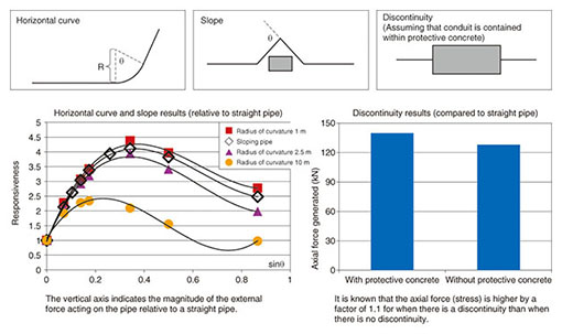
The investigation revealed relatively high damage rates for facilities that had protective concrete within the span (higher than the overall rate by a factor of 2.8) and for curved facilities with a radius of curvature of 100 m or less (higher by a factor of 1.3). To quantify the susceptibility to damage, three types of conduit lines—curved conduit, conduit laid on a slope or gradient, and conduit enclosed in protective concrete (referred to as a discontinuity)—were modeled, and a numerical analysis was executed. By comparing the results with the analysis results for straight conduit with no linear deviations, we were able to evaluate the effects of the line type of conduit during a large-scale earthquake. The results are shown in Fig. 7. Compared to the external force applied on straight conduit, the force is up to 3.5 times higher for curved installations and up to 4 times higher for sloping conduit. With protective concrete, the force is about 1.1 times that of conduit without protective concrete. Although the analysis is very simple, and more detailed model settings and numerical analyses are required, we can nevertheless identify which types of conduit may have weak points during a large-scale earthquake. In the future, we will conduct a numerical analysis using more detailed conduit models.
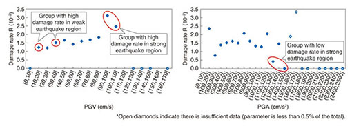
3.3 Factoring in the ground environment of underground conduitIn this section, we describe how the ground conditions affect the estimation of damage to conduit during an earthquake. For example, the liquefaction phenomenon was responsible for many incidents of damage that occurred to NTT conduit during the Great East Japan Earthquake in 2011. To quantify the effects of the ground environment on damage, NTT Access Network Service Systems Laboratories performed analyses using ground data and facilities data. The ground data used in the analysis were earthquake magnitude, peak ground velocity (PGV), and geomorphological classification (e.g., whether it was reclaimed land). The facilities data used for the analysis included data on a few hundred spans for which damage was confirmed and approximately 20,000 spans for which there was no damage. A geographic information system (GIS) was used in the analysis to investigate the correlation between the ground conditions and damage. The damage ratio was calculated by focusing on the facility attributes such as the age or type of pipe, the magnitude of the earthquake, and the ground conditions. The results are shown in Fig. 8.
The group of conduit pipes in regions where strong earthquakes occurred had a high damage rate, and the group subjected to earthquake motion with a PGV of 90 cm/s or more in particular had a damage rate of about 3%, which is high compared to the other groups. Closer examination of this group revealed that a lot of the damaged conduit in the group was buried in ground whose micro-geomorphological class is backswamp, which is generally weak ground, and a lot of the damaged conduit was a type that was introduced prior to the current standards. In other words, the analysis revealed that old standard conduit in weak ground has a high damage rate. A group with a low damage rate was also confirmed, even though the samples in this group were located in regions where strong earthquakes had occurred. The PGA (peak ground acceleration) was about 1400 cm/s2, and the damage rate in that group was 0.5%, which is lower than in other groups. Most of the conduit in that group was constructed based on current standards. These results indicate that the current standards for earthquake resistance are superior to the former standards. In contrast, a group of conduit that exhibited a damage rate of 1% in weak earthquake regions where the PGV was around 30 cm/s was also confirmed. This value is about the same as the damage rates of other groups subjected to strong earthquake motion. An examination of the feature attributes of that group revealed that in many cases, the conduit conformed to the old standards and was buried in reclaimed land. In other words, the damage rate was high for old standard conduit buried in areas where liquefaction occurred. The three tendencies concerning ground environment described here are the same as previous qualitative conditions under which conduit was found to be susceptible to damage during earthquakes in previous qualitative studies. Nevertheless, these results can be considered important for improving the prediction of earthquake damage on the basis of data on underground facilities and the ground environment. 4. Future developmentVarious factors other than the need to implement earthquake resistance measures may lead to updating of the telecommunication infrastructure. These include aging of facilities, insufficient capacity of facilities, eliminating redundancy in relay cable routes, economizing construction work done by other companies or done collaboratively, and rerouting. It is necessary to implement measures that combine these factors. The technology reported here has contributed to the improved reliability of important telecommunication routes by identifying the weak points that are most likely to be damaged in earthquakes. References
|
||||||||