|
|
|
|
|
|
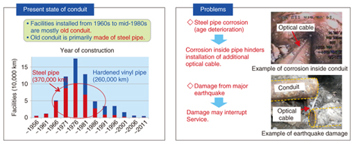
Feature Articles: R&D on Maintenance and Management Technologies for Telecommunication Infrastructure Vol. 12, No. 10, pp. 38–46, Oct. 2014. https://doi.org/10.53829/ntr201410fa6 Effective Repair and Reinforcement Technology for Conduit FacilitiesAbstractConduit facilities are located in every part of the country. As the huge number of conduit facilities deteriorate because of age, the cost of renovation and repair as well as maintenance and management increases, there is concern that network reliability may decline as a result. The development of conduit renewal techniques that use new technology and new materials will enable us to achieve the most effective use of conduit facilities and will contribute to reducing costs and maintaining a highly reliable network. This article describes newly developed maintenance and management technologies for buried conduit and conduit attached to bridges. Keywords: infrastructure facilities, repair technology, permanence of facilities  1. IntroductionThe telecommunication infrastructure supports a wide variety of information and telecommunication services that use telephones and the Internet. Part of that infrastructure consists of about 630,000 km of underground telecommunication conduit managed by NTT, and 70% of that conduit is at least 30 years old. A high proportion of old conduit is made of steel pipe, which has a strong tendency to deteriorate with age, so the number of degraded facilities is expected to increase. While we are continuing to improve facilities based on what we have learned from past major earthquakes, most old conduit was designed on old standards and therefore has low resistance to earthquakes. We must therefore take measures to prevent large-scale damage of these facilities in order to improve network reliability (Fig. 1).
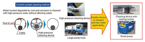
Maintaining telecommunication reliability through efficient maintenance and operation of the immense number of aging conduit facilities is a problem in view of the limited resources. For underground conduit, the steadily progressing facility degradation and the on-going transition to optical transmission create concerns about whether there is sufficient space to accommodate underground cables. To address these concerns, we developed and introduced technology for repairing cable conduit that also creates extra cable space and improves resistance to earthquake damage. We are working on applying the technology to more types of conduit and reducing the repair cost. Steel conduit that is attached to bridges is exposed to various conditions that promote corrosion. These include repeated wet and dry cycles because of rain, being sprayed with anti-freezing agents in winter, exposure to airborne salt in coastal regions, and various other severe environmental conditions. We are currently developing technology for safely cutting cable conduit and replacing degraded conduit with corrosion-free fiber reinforced plastic (FRP) pipe, which we plan to apply to corrosion-degraded conduit attached to bridges. We are also working on technology for reducing OPEX (operating expenses) by preventing the progression of rusting and extending the effective lifetime of coating materials. 2. Underground conduit repair technologyNew optical cable is being laid in the transition to optical transmission, and the use of multiline cable (laying multiple cables in a single conduit) is increasing in order to effectively use the limited underground cable accommodation space. However, about 52% of the conduit for which multiline-cable laying is planned has been diagnosed as degraded by rust or corrosion to an extent that prevents the use of multiline cable. As a result, roads have been excavated to add or reroute conduit, and some conduit has been repaired using the cut-and-cover method. However, cut-and-cover repairs are expensive and time-consuming. They also cause many environmental problems such as traffic congestion and noise, and they result in excess soil remaining after excavation. Therefore, a different solution is needed. We focused on finding a more effective method to repair steel conduit that contains optical cable and consequently developed technology for removing the rust and corrosion that causes degradation. The technology can be applied while the existing cable remains in place. We also developed conduit repair and rehabilitation technology that has wide applicability. These technologies and their most recent states of development are described in the following sections. 2.1 Technology for cleaning cable conduitThis technology uses high-pressure water to remove rust and corrosion from conduit that contains cable without affecting the cable (Fig. 2). An existing technique is capable of cleaning conduit up to 150 m in length. However, it requires a large truck equipped with a high-pressure pump that is expensive and has restrictions on how it can be used in construction. To overcome these problems, we developed a compact cleaning unit that can be used for small-diameter conduit and can accomplish the cleaning with a smaller, general-purpose pump. For effective cleaning with a lower pump output, we devised a rotating nozzle that has smaller holes, as shown on the right side of Fig. 2. We also developed a low-friction hose for cleaning longer lengths of pipe. It can safely work at distances of up to 250 m. This technology expands the application range, makes the system more flexible to use, and reduces cost by approximately 30% relative to current methods. The rotating nozzle cleaning head will be introduced in the second half of fiscal year (FY) 2014.
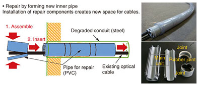
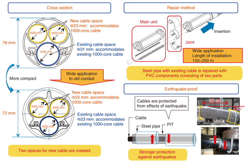
2.2 Technology for repair and rehabilitation of cable conduitThe PIT (pipe insertion type) new conduit method is used to repair conduit that has existing cable in place. It uses components that have an upper part and lower part made of PVC (polyvinyl chloride) and that are assembled around the existing cable. The components are 23 cm long and are connected end-to-end and pressed into the conduit that is being repaired to form a new pipe (Fig. 3). The entire conduit that is to be repaired becomes a double pipe, with the pipe formed by the repair component inside the original conduit. Even though the outer steel pipe has degraded with age, the inner repair pipe is strong, so the resulting structure is maintenance free. The repair also has no effect on the existing cable, so there is no interruption of service during the repair. The repair involves no excavation of roads and no open cuts, so it is less expensive and has no negative environmental effects. The repair also creates two new cable accommodation spaces, making a total maximum capacity of 3000 cores (1000 × 3). The double structure created by the repair also increases the resistance to earthquake damage and improves facility reliability.
The PIT new conduit method was first introduced by NTT EAST and NTT WEST in 2012, but its application was limited. For example, the maximum length of conduit that could be repaired was 150 m, and it also could not be used for older, small-diameter conduit. We therefore worked to expand the applicability of the technology. We reconsidered the component design in order to extend the length of conduit that could be repaired. We also changed the structure so it could better withstand the thrusting force generated when the units are pressed into the conduit being repaired, thus extending the repairable length to 250 m. We also revised the component structure so it could be applied to older, small-diameter conduit. The outside diameter of the modified component is smaller, so the cable accommodation capacity is also smaller. However, the existing cable accommodation space is also smaller, (small-diameter, 1000-core optical cable or less), we were able to make the newly created cable space the same as for current components, thus securing space for 3000 cores (3 small-diameter, 1000-core optical cables). In this way, we expanded the application range of the PIT new conduit method to older, small-diameter conduit. We also confirmed that the new design can withstand earthquake forces just as well as or better than the current vinyl pipe (Fig. 4). This technology is planned for commercial introduction in the latter half of FY2014.
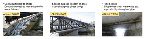
3. Technology for repairing conduit attached to bridgesNTT’s approximately 50,000 bridge facilities include conduit attached to bridges, special-purpose telecommunication bridges, and pipe bridges (Fig. 5). About 20% of these bridge facilities require repairs. Those that have advanced deterioration due to age are being repaired by replacing the conduit, and those that have surface rusting are being repainted. The current replacement repair technique is limited in the length of conduit that can be replaced due to the insufficient strength of FRP pipe. Also, when the gap between conduits is small, there are places where the conduit cannot be cut. We are therefore working on ways of expanding the range of applications of this technique.
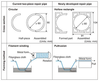
The conduit coating technology we are currently using involves the use of an economical and commercially available coating technique. However, this technique cannot keep up with the increasing quantity of age-degraded conduit, so we are developing technology for greatly extending the service life of conduit coatings. These technologies are described below. 3.1 Replacement-repair technologyThe replacement technique to repair corrosion-degraded cable conduit attached to bridges involves replacing the corroded section of the steel pipe with two-piece FRP repair pipe. This technique was introduced commercially in FY2008. However, the application of this technique was limited to conduit where the distance between supports was L = 2.5 m or less. The main reason for this restriction is that the rigidity of the currently used two-piece repair pipe is insufficient to satisfy the permissible deflection (L/300 or less) under load (cable and snow). Applying the current technology with additional supports deviates from the original bridge design, so it is often not possible to obtain permission to modify the structure from the road managing authority, and such repairs then cannot be done. To solve this problem, we developed long and highly rigid FRP repair pipe that can be used to extend the replacement-repair technique to cable conduit where the distance between supports (L) is up to 5.5 m. The current repair pipe has a circular cross section and is formed by the filament winding method, in which fiberglass cloth is wrapped circumferentially. However, the cross-section shape and material rigidity of this method does not provide sufficient strength for repairs longer than L = 2.5 m, as described above. Furthermore, a process for splitting the formed pipe into two pieces is required, which adds to the manufacturing cost. By developing a repair pipe that has a hollow rectangular cross section, we efficiently increased the cross-sectional rigidity. This new repair pipe is formed by pulling fiberglass cloth out in the axial direction of the pipe, thus increasing the material rigidity against perpendicular loads. This is called the pultrusion method, and it can be applied to any cross-section shape, so formed parts that have left-right symmetry can be assembled into repair pipe, thus eliminating the splitting process and reducing the manufacturing cost (Fig. 6).
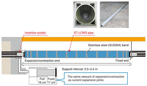
This repair pipe is strong and highly resistant to bending and degradation. It is called ST-LONG pipe, which is derived from square-type, long length FRP pipe. Also, to reduce the splitting cost, we adopted the pultrusion method for the insertion sockets, which are used for joining ST-LONG pipe and existing steel pipe to complete the replacement repair. Because the old facilities to which replacement repair is applied have little capacity for expansion and contraction, there is concern about possible damage due to disconnection or buckling at the joints in an earthquake. We therefore designed the joints to have the same amount of expansion and contraction as current expansion joints, thus improving their resistance to earthquake damage in addition to enabling completion of the repair (Fig. 7).
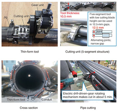
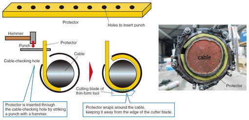
The results of testing prototype ST-LONG pipe and insertion sockets for bending, strength, and vibration resonance with bridge structures confirmed that the developed components satisfy the permissible deflection at L = 5.5 m and that the strength and resistance to resonance effects are sufficient. We also evaluated repair workability with a model for conduit attached to a bridge. The results showed that the developed components provide good workability for multiple cable-conduits. 3.2 Expanding the applications of conduit cutting technologyIn places where the gap between conduits is less than 30 mm, the corroded part cannot be cut out and removed, so the current two-piece FRP repair pipe cannot be used for replacement repair in such cases. Conduit attached to bridges is installed densely because of the limited space, so narrow gaps between conduits are common. Replacement repair is performed using three main steps. Step 1) Check whether or not conduit has cable. Step 2) Cut and remove degraded conduit. Step 3) Attach repair pipe. The reason the corroded parts often cannot be cut and removed in step 2 is that current pipe cutting tools cannot be inserted into the narrow gap between the conduits. Also, the cutting is done manually using existing cutting tools, and this is inefficient for on-site work. The technology we developed uses a low cutting blade height to achieve a low-profile pipe cutter (thin-form tool). The cutting unit is constructed of five segments and can easily be inserted into narrow gaps. As a result, the unit can be inserted into a gap as small as 12.5 mm, which is the narrowest gap assumed for places where conduit joints are installed in an alternating configuration. Furthermore, higher cutting efficiency is achieved by using a rotating cutter that has a gear mechanism driven by an electric drill. Whereas the current cutting tool requires about 15 minutes to make one cut in a conduit, this thin-form tool requires only about 5 minutes (Fig. 8).
Another problem with the current cutting method is that there is no protection for the cable inside the conduit. The reason for the lack of protection is the difficulty of inserting a protector into the conduit. To solve this problem, we developed a simple and sure cable protection method to apply when the thin-form cutting tool is used. The method involves inserting a long, narrow protector through the hole used to check for cable in step 1 so that it wraps around the cable inside the conduit and keeps the cable away from the edge of the cutter blade. This prevents contact between the blade and the cable, ensuring protection of the cable during the cutting process. The protector is inserted by using a hammer in an operation that is easy to do even with thick and heavy cables. We evaluated a variety of materials for ease of insertion, strength, and cost, and selected 5.0-mm-thick polyethylene foam sheeting as a sample material to be used for the cable protector (Fig. 9). Commercial introduction of this protection technique for use together with the replacement repair technique described above is planned in FY2014.
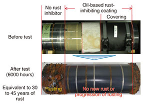
3.3 Coating repair technologyConduit that has superficial rusting where the corrosion is not severe is repaired by removing the rust and coating the affected area with polyurethane paint to prevent further corrosion. The purpose of repairing the conduit at the stage of light rusting is to halt the progression to the stage of corrosion degradation in which replacement is necessary. Currently, three coats of a polyurethane resin and epoxy resin rust-proofing agent are used. The coating is effective for 10 to 15 years, but this approach cannot keep up with the increasing number of deteriorating facilities. We are therefore working on rust-proofing technology that remains effective for 40 years or more. The results of accelerated degradation tests performed in cooperation with the NTT Energy and Environment Systems Laboratories indicated that oil-based rust-proofing using wool wax is effective (Fig. 10). We found that rusting progressed after 2000 hours for currently used coatings (polyurethane resin), but there was no rusting after 6000 hours with an oil-based coating, which confirmed an improvement in durability by a factor of three or more.
The results of temperature and coating thickness tests showed that securing the target lifetime of 40 years requires a thickness of at least 0.5 mm of a cream-type oil-based rust-proofing agent. However, that type of rust-proofing agent does not harden, so it would be difficult to maintain the required thickness over the required period of time. We are therefore investigating methods for using oil-based rust-proofing on conduit attached to bridges. Currently, the required coating thickness can be maintained by using cloth impregnated with the oil-based rust-proofing agent that is wrapped around the conduit. Therefore, we are continuing our efforts towards making this technique practical for use on bundled facilities and in places where the gap between conduits is small, aiming for commercial introduction in FY2015. 4. Future issues and prospectsMost of the NTT conduit facilities are buried beneath roads. Work on repairing or widening roads, sidewalk maintenance work, or work done on the underground facilities of other companies may disturb existing NTT conduit facilities or result in the need to relocate them. For spans that cross rivers, the facilities may also need to be relocated when NTT conduit attached to bridges and bridge facilities are rebuilt, reinforced against earthquakes, or painted. We are also working on technology for reducing construction costs in order to deal with facility relocation. For cases in which new facilities are constructed after relocation, we will continue to investigate simple and economical facility designs that can flexibly cope with changes in capacity and transmission medium specifications, keeping future all-optical transmission in mind. The increasing number of NTT conduit facilities that are degraded by aging and other factors remain a concern for the future. We will continue developing new technology to solve such problems and contribute to achieving higher network reliability. |