|
|||||||||||||
|
|
|||||||||||||
|
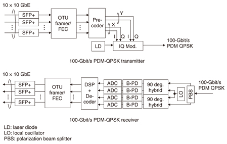
Feature Articles: Movable and Deployable ICT Resource Unit—Architecture for Quickly Responding to Unexpected ICT Demand Vol. 13, No. 5, pp. 12–16, May 2015. https://doi.org/10.53829/ntr201505fa3 High-speed and Plug-and-play Optical Interconnection for MDRUsAbstractAfter a Movable and Deployable ICT Resource Unit (MDRU) is installed and local ICT (information and communication technology) services are established in a disaster-affected area, reestablishing communication service between the disaster-affected area and undamaged areas will be strongly desired by the people in the disaster-affected area. We propose to establish a communication link between the MDRU and the backbone network by connecting 100-Gbit/s digital coherent transponders to the ends of undamaged underground optical cable. Keywords: movable and deployable ICT resource unit, digital coherent technology, plug and play  1. IntroductionThe Movable and Deployable ICT Resource Unit (MDRU) can be easily transported to damaged areas and used to quickly establish local information and communication technology (ICT) services once it is installed. A Wi-Fi based access network is formed with a radius of several hundred meters from the center of the MDRU; it allows public and municipal employees to communicate with others in the area. In addition, because the MDRU has a datacenter function, it can provide various custom ICT services to local government, hospitals, and the police and fire departments. However, these services are available only within the limited area around the MDRU, and another strategy is necessary to reestablish communications with those outside the damaged area. There are two main approaches to connect an MDRU to the backbone network. One is to use satellite communications, and the other is to use optical communications. Each approach has advantages and disadvantages, so the selection depends on the situation. Satellite interconnection makes it possible to avoid the physical difficulties present in the disaster area, although the transmission capacity is limited. For example, only a limited number of conversations can be conducted simultaneously between people in the damaged area and people in undamaged areas. In contrast, while optical communications offer massive capacity, there may be few facilities available if the damage is severe. However, optical fiber cables laid underground are thought to be robust against disasters. In fact, we (the NTT Group) found that many optical fiber cables remained viable even after all surface structures and equipment had been washed away by the tsunami after The Great East Japan Earthquake. This means that optical links could be established if we could use the undamaged optical fiber cables. We recently proposed a method to connect an MDRU to the backbone network by using optical fiber cables laid underground [1]. In this article, we explain our method and describe a proof-of-concept demonstration. 2. Optical interconnection requirements: MDRU to backbone networkSeveral difficulties arise when connecting an MDRU to the backbone network via optical links established on optical fibers, as follows. (1) It is very difficult to immediately obtain comprehensive information on cable parameters (fiber type, length, etc.) in the damaged area. (2) Transmission capacity will need to be expanded because the standard voice service will be replaced by a visual information service that needs a wider bandwidth as reconstruction progresses. (3) Prompt and flexible reconfiguration of the optical network will be needed in the damaged area because the situation can easily change. This means that the optical path can often change. (4) When we connect an MDRU to a faraway datacenter in an undamaged area by optical networking only, long-distance optical transmission is needed, which requires chromatic dispersion compensation. In considering these difficulties, we arrived at the conclusion that a 100-Gbit/s digital coherent transponder should be installed in both the MDRU and a working telecommunication building to enable optical interconnection. A digital coherent transponder can equalize optical signal waveforms automatically by electrically compensating the chromatic dispersion of fibers, so it is therefore expected that optical interconnection can be immediately established by connecting the transponders to the ends of the fiber cables, even though the fiber parameters may be unknown. In addition, the optical interconnection will be immediately reestablished after switching optical fiber cables for rerouting. To verify the above concept, we developed a prototype of a 100-Gbit/s digital coherent transponder and experimentally confirmed the robust and immediate connection by virtue of its plug-and-play functionality. 3. Optical channel recovery experimentThe configuration of our prototype 100-Gbit/s digital coherent transponder for an MDRU is shown in Fig. 1. The prototype is based on a standard 100-Gbit/s polarization-division multiplexing (PDM) quadrature phase-shift keying (QPSK)*1 transponder [2] and can compensate the maximum chromatic dispersion (CD) of 40,000 ps/nm. The transponder accommodates ten channels of 10-Gbit/s Ethernet (10GbE) client data, and ten SFP+ (small form-factor pluggable+) modules*2 can be installed on the input/output interface part. The 10GbE client data are multiplexed into 100-Gbit/s optical transport network (OTN) signals*3 through an optical-channel transport unit 4 (OTU4) framer and with forward error correction (FEC) overhead. The data are realigned to 4 × 32-Gbit/s sequences and fed into an optical IQ (I: In-phase, Q: Quadrature) modulator for QPSK modulation and polarization multiplexing. The transmitted 100-Gbit/s PDM-QPSK signal is received by a digital coherent receiver; I and Q data for each polarization are obtained with a polarization-diversity 90 degree optical hybrid and balanced photodetectors (B-PDs), and digitized with a four-channel analog-to-digital converter (ADC). In the digital signal processing (DSP), CD compensation, polarization demultiplexing and adaptive polarization mode dispersion (PMD) equalization, and frequency-offset compensation and carrier-phase recovery are carried out for the 4 × 32-Gbit/s data, followed by error correction and demapping to 10 GbE.
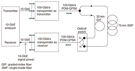
We evaluated how fast the optical channel could be recovered when the 100-Gbit/s transmission link was switched between different types and lengths of fibers by a mechanical fast optical switch whose switching time was less than 1 ms. The experimental setup is shown in Fig. 2. The 10GbE client data are supplied by a 10GbE analyzer and converted to 100-Gbit/s signals in the transmitter. The transmitted signals are received, and the converted 10GbE client data are fed via another short fiber to the 10GbE analyzer, which counted the received bytes with a resolution of 1 ms. This enabled us to evaluate the influence of link switching on the throughput of the client 10GbE data. The point at which we measured the 10GbE signal power is also shown in Fig. 2 by the arrow in the lower left of the figure.
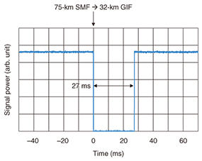
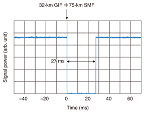
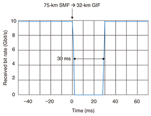
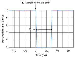
We evaluated how fast the optical channel could be reestablished when the link was switched from a 75-km single-mode fiber (SMF) to a 32-km graded-index fiber (GIF) and vice versa. The evolution of the received 10GbE optical signal level is shown in Fig. 3 and Fig. 4. After the link was switched, the 10GbE signal output was shut down and remained quiescent for 27 ms until the signal level returned to normal. This indicates that once the channel was disconnected, the DSP was able to complete channel re-estimation and synchronization within 27 ms. The outage time is the same in Fig. 3 and Fig. 4, which indicates that recovery time is independent of the fiber type and length.
For comparison, we measured the evolution of the received 10GbE data traffic associated with the switching by using a 10GbE analyzer; the results are shown in Fig. 5 and Fig. 6. The horizontal axis is the elapsed time after channel switching, and the vertical axis shows the net bit rate calculated from the number of bytes received without failure. The 10GbE traffic recovers after 30 ms. The 3-ms difference from Fig. 3 and Fig. 4 may be due to the processing time in the 10GbE receiver module. Also, it is concluded that a 100-Gbit/s digital coherent transponder can compensate the modal dispersion*4 of a GIF about 30 km long.
The measured switching performance suggests that the transponder offers true plug-and-play functionality and that fiber parameters do not need to be measured. Thus, the transponder is expected to be effective after disasters for interconnecting MDRUs to the backbone network through underground optical fiber cables.
4. Perspective on optical interconnection for MDRUIn conclusion, with the plug-and-play functionality based on digital coherent technology, an MDRU can be immediately connected to the working backbone network via an undamaged underground optical fiber cable. We note that not all MDRUs will be sited close to optical fiber that offers unbroken connection to the backbone, as they will usually be placed next to evacuation centers or public facilities. Thus, we will have to interconnect the MDRUs. If there is no physical obstruction between two MDRUs, we can connect them by fixed wireless access. However, when physical obstruction is unavoidable, one alternative is to reuse parts of the underground optical fiber cable that are still viable. To realize the above optical interconnection using underground cables, we need to obtain prior agreement from communication carriers and to carry out technical preparations for the connections to the backbone network. For example, we have to obtain agreement as to how or where to set a transponder in a telecommunication building. It is also necessary to develop a way of finding or selecting optical cables in disaster areas and protocols to confirm the corresponding cables in working telecommunication buildings. This will definitely require the support and assistance of communication carriers. In addition, we will have to consider using the optical cables of noncarriers such as local governments. 5. SummaryWe proposed the application of digital coherent technology to interconnect MDRUs in a disaster area with the backbone network via working telecommunication buildings and underground optical fiber cable. We experimentally confirmed the plug-and-play functionality achieved using digital coherent technology. We also discussed problems that remain to be solved from a practical application perspective. AcknowledgmentsPart of the work in this article is being conducted under the national projects, R&D on the reconfigurable communication resource unit for disaster recovery and R&D of “Movable ICT Units” for emergency transportation into disaster-affected areas and multi-unit connection, both supported by the Ministry of Internal Affairs and Communications of Japan. References
|
|||||||||||||