|
|
|
|
|
|
Regular Articles Vol. 13, No. 7, pp. 55–61, July 2015. https://doi.org/10.53829/ntr201507ra3 Cross-connect System with Packet Transport TechnologyAbstractThe public switched telephone network (PSTN) and existing dedicated line services have been carried over transmission lines using older data link systems based on time-division multiplexing technology. However, as Internet protocol traffic has increased and traffic to the PSTN and existing dedicated services has decreased, there has been a move to use data link systems based on packet transport technology; this in turn has allowed simpler networks to be built. We have developed a packet-based cross-connect system that can efficiently promote this transition by allowing individual low-speed (1.5 Mbit/s) paths to be split up and reassembled. Keywords: SDH, MPLS-TP, cross-connect system  1. Introduction1.1 Development goalsThe old data link system and existing dedicated line system were adopted more than 20 years ago, and they have begun to show signs of age. Consequently, replacement parts need to be secured, the cost of maintenance is rising, and there is a shrinking number of technicians familiar with the equipment. NTT Network Service Systems Laboratories is working to address these issues by developing technologies for migrating away from the old data link system and the existing dedicated line system. However, the increase in Internet protocol (IP)-related traffic together with the reduction in traffic to the public switched telephone network (PSTN) and existing dedicated line services means that any future network needs to be able to:
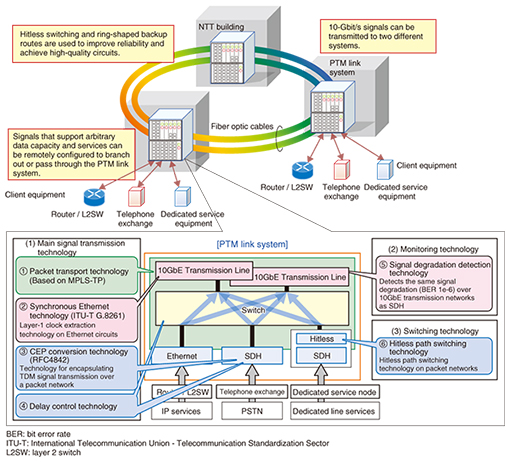
1.2 Technologies appliedTo satisfy these conditions, NTT Network Service Systems Laboratories has developed a Packet Transport Multiplexer (PTM) link system based on this packet transport technology. An overview of the PTM link system is shown in Fig. 1. The following signal transmission technologies are used in the PTM system: packet transport technology based on Multiprotocol Label Switching - Transport Profile (MPLS-TP), Synchronous Ethernet technology that can extract layer-1 clocks over the Ethernet physical layer, CEP (circuit emulation over packet) conversion technology that encapsulates time-division multiplexing (TDM) signal transmission over a packet network, and delay control technology that can forward data over packet networks with the same delay as conventional SDH.
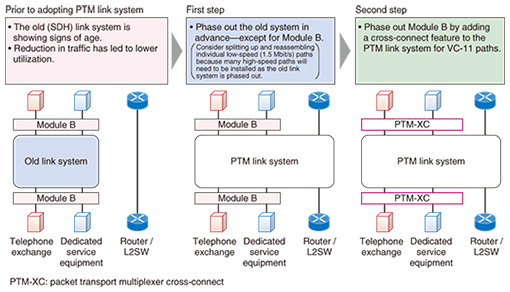
For monitoring, the PTM link system uses signal degradation detection technology that can detect the same amount of signal degradation (bit error rate: 10−6) as SDH over the Ethernet physical layer. For switching, the PTM link system uses hitless path switching over packet networks. The PTM link system is an infrastructure system that will form the basis of NTT’s telecommunications network with the same quality of data transmission as synchronous transport modules (STMs), which can provide TDM services for PSTN and dedicated lines over packet networks. The PTM link system integrates both TDM and packet technology; it can multiplex and demultiplex paths of arbitrary capacity at any datacenter, allowing the network to dynamically adjust in response to demand and the type of service provided. 1.3 Migration processDevelopment at NTT has proceeded in anticipation of a two-step migration process. The previous-generation link system will be migrated first (as shown in Fig. 2), followed by the equipment referred to as Module B. The Module B cross-connect equipment has STM-0/STM-1 interfaces (52M/156M IF) for connecting VC-11 (virtual container 11: 1.5 Mbit/s) paths between any STM-0/STM-1 interfaces.
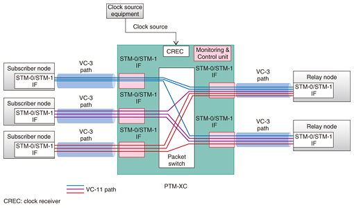
Subscriber nodes and relay nodes for PSTN and dedicated services will be connected to each other via VC-3 (52 Mbit/s) paths in the future. As a result, we can bundle several low-speed VC-11 and VC-2 (6.3 Mbit/s) path segments with low utilization in the VC-3 path to increase path utilization and enable more efficient migrations. This approach will also be used for connections between businesses and at other times when it is difficult to transition to VC-3 paths. To improve path utilization, we developed a PTM-XC (PTM cross-connect) system with cross-connect features for VC-11 and VC-2 paths. An overview of the PTM-XC is shown in Fig. 3.
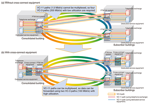
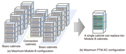
By basing PTM-XC on a PTM link system with packet switches, we were able to use common parts and minimize the scope of development. 2. Issues of migrating away from existing equipment (Module B)The equipment for Module B was adopted over 20 years ago, so we need to consider the following issues in the PTM-XC migration. 2.1 High-efficiency, high-density utilizationThe utilization of existing equipment has dropped with the decrease in traffic to the PSTN and existing dedicated line services. For this reason—and because many more VC-3 paths will need to be installed when the old link system is phased out—we aim to achieve higher utilization by splitting up and reassembling individual VC-11/VC-2 paths. Sample connections from a single consolidated building to two subscriber buildings using telephone exchange and dedicated service equipment are shown in Fig. 4. Without the cross-connect equipment, VC-11 paths (1.5 Mbit/s) cannot be multiplexed, and thus, four under-utilized VC-3 paths are required. By introducing cross-connect equipment, we can multiplex VC-11 paths and thus establish connections via two VC-3 paths with high utilization. Furthermore, ten Module B units are necessary to accommodate the maximum number of (VC-11) paths—4032—when utilization is high. These Module B units occupy a large area once they are installed. We wanted PTM-XC to accommodate the same number of paths as Module B in a denser package to reduce this installation size.
2.2 Reduced delayPTM-XC must reduce the delay for the existing dedicated line services that it accommodates at least as much as Module B does. In general, the conversion of VC-11/VC-2 signals to MPLS-TP packets—and vice versa—incurs considerable delay that we want to minimize. 2.3 Reduced power consumptionModule B can comprise up to ten units, so its energy consumption is significant and its operational costs are increasing. The demand for energy conservation has increased in recent years, and therefore, we want PTM-XC to use less power than its predecessors. 2.4 Improved maintainabilityCross-connect equipment must be able to accommodate up to 4032 (VC-11) paths; it also comes equipped with a large number of packages and optical modules, which we want to make easier to register. In addition, there are numerous interfaces that connect the Module B cabinets to each other. As a result, it can be difficult to pinpoint malfunctions in the interfaces between sending and receiving units. We want PTM-XC systems to be easier to maintain, allowing technicians to quickly find and repair any malfunctioning parts. Furthermore, semiconductor devices have become more integrated and intricate in response to recent demands for equipment that is smaller and consumes less power. This has made it possible for soft errors (such as bit errors in memory attributed to cosmic rays) to occur and cause malfunctions. We also want to address these soft errors. 3. Technical solutions to address these issues3.1 High-efficiency path utilizationPTM-XC’s cross-connect features use MPLS-TP paths (label switched paths) to forward information between packages, placing information about the destination in internal headers. Internally, the equipment uses MPLS-TP to encapsulate the two-way connection between the STM-0/STM-1 interface and the switch when forwarding data from the input port (A) to the output port (Z). By multiplexing several VC-11/VC-2 paths going in the same direction, we were able to keep the overhead for packetizing data in check. Also, we were able to use a single cabinet to accommodate the same number of circuits that would have required ten cabinets with existing equipment, as shown in Fig. 5.
3.2 Low-delay technologyTo suppress the delays associated with packetizing and depacketizing data when paths are respectively multiplexed and demultiplexed, TU (tributary unit)-11/TU-2 frames are split when they are packetized. This has resulted in processing delays equivalent to or less than Module B. 3.3 Reduced power consumptionWe have managed to reduce the number of circuits from ten cabinets’ worth with Module B, the existing equipment, to only a single cabinet’s worth. This has allowed us to reduce the maximum power consumption levels to approximately 5% of Module B’s. 3.4 Improved maintainability and operabilityPTM-XC automatically registers monitoring controllers, switches, STM-0/STM-1 interfaces, and other packages in every slot when unit types are configured during the construction of new equipment. Multiplex section protection is automatically configured for all identical ports in adjacent slots when the STM-0/STM-1 interfaces are registered, reducing the steps necessary to open paths. PTM-XC also does not require any complicated connections between cabinet interfaces because it only uses a single cabinet in its maximum configuration; instead, it simply uses STM-0/STM-1 interfaces and switches. As a result, PTM-XC is easier to troubleshoot than Module B, which could involve problems spanning multiple cabinets. PTM-XC furthermore provides the same path testing features as Module B, making it easy to pinpoint where errors have occurred. In addition to everything mentioned above, PTM-XC takes measures to automatically correct soft errors that can occur in both main signal memory and monitoring controller memory. PTM-XC also provides performance-related information by counting the number of soft errors that occur and sending notifications when a given threshold of errors is exceeded. When a package needs to be replaced, a remote technician can make that package’s light-emitting diodes alternately blink red and green to point it out to an onsite technician. 4. SummaryIn this article, we introduced PTM-XC equipment that was developed by NTT Network Service Systems Laboratories and is capable of splitting and reassembling individual low-speed (1.5 Mbit/s) paths. PTM-XC can make the process of migrating away from existing Module B equipment efficient and cost-effective. We are aiming to push forward on migrating to a link system with this equipment and support simple network structures in the future. |