|
|||||||||||||||||
|
|
|||||||||||||||||
       |
Feature Articles: State-of-the-art Space Division Multiplexing Technologies for Future High-capacity Optical Transport Networks Vol. 15, No. 6, pp. 23–28, June 2017. https://doi.org/10.53829/ntr201706fa4 Optical Amplification Technologies for Space Division MultiplexingAbstractTechnologies that enable simultaneous optical amplification of spatially multiplexed optical signals are essential for a long-haul space division multiplexing (SDM) transmission system that employs a multi-core fiber and/or few-mode fiber. This article introduces optical amplification technologies that make it possible to construct a multi-core erbium-doped fiber amplifier (EDFA) and a few-mode EDFA for SDM transmission. Keywords: multi-core fiber amplifier, few-mode fiber amplifier, erbium-doped fiber
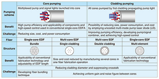
1. IntroductionAn optical amplifier is necessary for a long-haul space division multiplexing (SDM) transmission system that employs a multi-core fiber and/or a few-mode fiber as a transmission line. SDM optical amplifiers utilize an erbium-doped fiber (EDF) as the amplification medium in the same way as the optical amplifiers used in the current single-core and single-mode fiber transmission system. An important function of SDM optical amplifiers is simultaneous amplification of spatially multiplexed optical signals. Two kinds of optical amplifiers have mainly been studied in recent years in order to realize such a function. One is a multi-core erbium-doped fiber amplifier (MC-EDFA), which employs a multi-core EDF that has multiple erbium cores within a single fiber. The other is a few-mode erbium-doped fiber amplifier (FM-EDFA), which utilizes a few-mode EDF that is a kind of multi-mode fiber. A few-mode EDF supports several propagation modes used for signal transmission and restricts unusable higher-order modes. 2. MC-EDFATable 1 categorizes MC-EDFAs in terms of pumping schemes and active fibers. There are two kinds of pumping schemes, namely core pumping and cladding pumping.
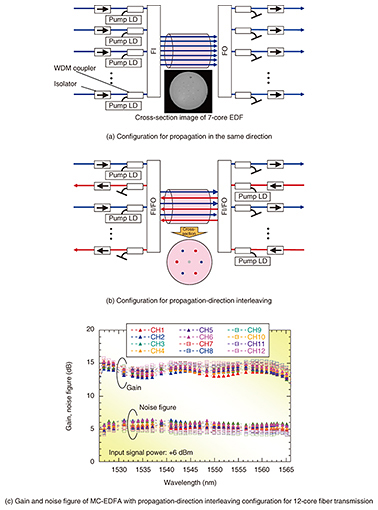
An MC-EDFA employing core pumping can employ optical components that are used for a conventional single-core EDFA. It provides high pumping efficiency and can also support conventional high-speed control to suppress the transient power caused by a change in the input signal power. The challenges to be met include integrating the optical components to reduce the total amplifier size, cost, and power consumption. Cladding pumping has the potential to achieve both low power consumption and downsizing by using an uncooled multi-mode pump laser diode (LD). Challenges include improving the pumping efficiency, developing optical components for launching the pump and multiple signal lights simultaneously, and devising a technique for adjusting the gain of several cores to achieve a pump power with high-speed control. Four kinds of active fibers have already been reported for multi-core amplification: a bundle of reduced-cladding EDFs, a multi-core EDF with a single cladding, a multi-core EDF with a double cladding, and a multi-element EDF. The bundle and multi-element EDFs can utilize conventional mature fiber fabrication techniques, and the lengths of different EDFs can be adjusted to achieve a uniform gain. A drawback is the necessity of downsizing the cross-section of the amplification medium. The benefit of multi-core EDFs with single and double cladding lies in the reduced cost, which is achieved by manufacturing several cores in one fiber fabrication operation. Another benefit of multi-core EDFs is that their cladding diameter is small compared with bundled and multi-element EDFs. Finding a way to achieve a uniform amplification characteristic for all the cores is a challenge for both multi-core and multi-element EDFs, and finding a way to suppress crosstalk is a common challenge for all active fibers. 2.1 Core-pumped MC-EDFAA typical configuration of a core-pumped MC-EDFA is shown in Fig. 1(a). Both the pump and signal lights are multiplexed with a wavelength division multiplexing (WDM) coupler and launched into an erbium-doped core through a fan-in (FI), and the amplified signals are output through a fan-out (FO). In this amplifier configuration, since the FI and FO can reverse the propagation direction of the signal lights, the propagation of the signal light in each core can be set in any direction. Setting the signal lights in two adjacent cores to propagate in opposite directions reduces the intercore crosstalk [1]. An MC-EDFA was constructed for long-haul transmission through 12-core fiber by employing this method. Its configuration is shown in Fig. 1(b). This MC-EDFA utilizes the outer cores of a dual 7-core EDF. As shown in Fig. 1(c), a gain of over 11.4 dB and a noise figure of less than 6.5 dB were achieved across the entire C-band when the signal lights of all the cores propagated in the same direction. The MC-EDFA was applied to SDM transmission with a capacity-distance product of 1 Ebit/s, and the results suggest its feasibility [2]. A bundle of reduced-cladding EDFs can also be used in this kind of SDM optical amplifier [3].
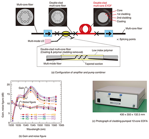
2.2 Cladding-pumped MC-EDFAThe configuration of a cladding-pumped MC-EDFA is shown in Fig. 2(a). To improve pumping efficiency, we employed double-clad multi-core erbium/ytterbium-doped fiber (DCMC-EYDF). In this fiber, the pump absorption is sensitized by transferring energy from the ytterbium to erbium ions and suppressing the clustering of erbium ions, which results in improved pumping efficiency. Twelve erbium/ytterbium-doped cores were arranged in a hexagon as shown in the figure. The core pitch is 37.2 μm, and the first and second claddings and the coating diameters are 216, 284, and 356 μm, respectively. The pump source was a 976-nm multi-mode LD with a 125-μm-diameter multi-mode fiber pigtail. A schematic of the pump combiner is also shown in Fig. 2(a). The pump combiner consists of a multi-mode fiber with a tapered section and the double-clad 12-core fiber, whose cross-sectional design was the same as that of the DCMC-EYDF. A short section of the double-clad 12-core fiber was stripped of its low refractive-index second cladding and coating, and the stripped section was rounded to form an optical contact with the tapered multi-mode fiber. The optical contact section was recoated with a low index polymer. This pump combiner was fusion-spliced to the DCMC-EYDF, which enables the pump light to couple to the first cladding of the DCMC-EYDF. Twelve-core isolators were located at the input and output ends of the amplifier to avoid laser oscillation. The gain and noise figure of the cladding-pumped MC-EDFA are shown in Fig. 2(b), and a photo of the device is shown in Fig. 2(c). The input signal was an 8-channel WDM signal with a power of −14 dBm/ch, and the pump power was 3.4 W. The optical amplifier exhibited over 10-dB gain and less than an 8.7-dB noise figure for all 12 cores at wavelengths longer than 1534 nm. In this case, the electrical power consumption was about 10 W, while the sum of that of 12 conventional EDFAs was estimated to be 20 W at an ambient temperature of 65ºC. This suggests that the cladding-pumped MC-EDFA successfully reduced the power consumption by about half that of the conventional optical amplifier.
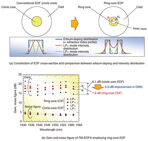
The cladding pumping was also adopted in an SDM optical amplifier for a dense SDM (DSDM) transmission. A 32-core EDFA that employed a DCMC-EYDF was used in a DSDM transmission experiment as an optical amplifier repeater [4]. The gain and noise figure of the cladding-pumped MC-EDFA with a DCMC-EYDF degraded in the shorter wavelength region because of the strong absorption of the erbium ions in the EDF. Further study is necessary to improve the uniformity of the gain and the noise characteristics if we are to use the entire C-band for amplification. 3. FM-EDFAOne issue with FM-EDFAs is the differential modal gain (DMG) needed to minimize the differences between the signal-to-noise ratios of all the transmitted signals and thus maintain signal quality. To reduce the DMG in FM-EDFAs, it is important to reduce the difference between two overlap integrals, namely that for the excited erbium ion area and the intensity distribution of the fundamental mode signal and that for the excited erbium ion area and the intensity profile of higher-order signals. For this purpose, the doping of erbium ions with a ring profile and the use of a reconfigurable pump mode have been reported [5, 6]. Disadvantages of these techniques are that the former complicates the EDF fabrication process, and the latter introduces an additional loss for the pump power. Another approach was taken in an NTT study, which involves employing a ring-core erbium-doped fiber (RC-EDF) with a ring-shaped index profile. As shown in Fig. 3(a), the optical signals of LP01 and LP11 modes at the RC-EDF have a similar intensity distribution, in which the overlap integral for both the LP01 and LP11 mode signals have similar values, resulting in a reduction of the DMG. Our approach has advantages over other approaches in that it maintains a simple fabrication process with uniform erbium doping and eliminates the need for lossy additional pump adjustment. The FM-EDFA with an RC-EDF whose parameters were optimized successfully exhibited a small DMG of 1.6 dB, which is 4.5 dB smaller than that for an FM-EDFA with a conventional circular core (Fig. 3(b)). The FM-EDFA with the RC-EDF was also used for a long-haul mode-division-multiplexing transmission as an optical amplifier repeater, which confirmed its feasibility [7].
4. Future workIn upcoming research, we will investigate advanced amplification technologies for gain and output control in SDM optical amplifiers. This study was undertaken as part of a collaborative project with Fujikura Ltd., Osaka Prefecture University, Shimane University, and Chitose Institute of Science and Technology. References
|
||||||||||||||||