|
|||||||||||||||||||
|
|
|||||||||||||||||||
|
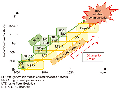
Regular Articles Vol. 15, No. 9, pp. 33–41, Sept. 2017. https://doi.org/10.53829/ntr201709ra1 Orbital Angular Momentum Multiplexing Technology towards the Realization of Tbit/s Wireless TransmissionAbstractWe explore the potential of orbital angular momentum (OAM) multiplexing towards enabling high-speed wireless transmission. OAM is a physical property of electromagnetic waves that are characterized by a helical phase front in the propagation direction. This characteristic can be exploited to create multiple orthogonal channels, and thus, wireless transmission using OAM can enhance the wireless transmission rate. We clarify two major issues in OAM multiplexing: beam divergence and mode-dependent performance degradation. To address these issues, we present a simple but practical receiver antenna design method. Because there are specific location sets with phase differences of 90 or 180 degrees, the method allows each OAM mode to be received at its high signal-to-noise ratio region. We confirm the feasibility of OAM multiplexing in a proof of concept experiment at 5.2 GHz. Finally, we briefly introduce the future directions of this work. Keywords: orbital angular momentum multiplexing, uniform circular array, 5G, millimeter wave  1. IntroductionSignificant progress has been made in wireless communication technologies in recent decades. In particular, the utilization of higher frequency bands (e.g., the millimeter-wave (mm-wave) band), where several gigahertz of bandwidth is available, has played a key role in achieving such progress. Recent research efforts have shown the feasibility and possibility of utilizing mm-wave technologies to provide transmission at up to several tens of gigabits per second [1]. Despite such achievements, providing high-order data-rate transmission is expected to be necessary to satisfy the ever-increasing demand for such transmission in the coming decade. We have also observed from history that the transmission rate of wireless communication has increased 100 times every 10 years, as shown in Fig. 1. Considering this trend and the current mature status of mm-wave technologies [1], we consider it is high time to discuss the candidates for wireless transmission technologies to provide up to 1-Tbit/s transmission.
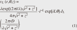
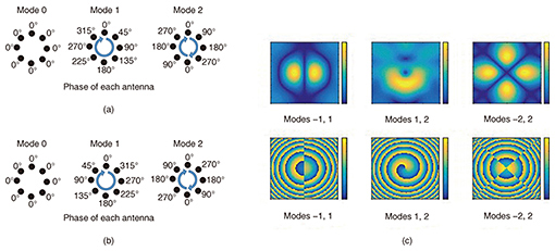
The orbital angular momentum (OAM) multiplexing method is an emerging wireless transmission technology that exploits a physical property of electromagnetic waves characterized by a helical phase front in the propagation direction [2]. The propagating beams with a distinct number of phase rotations, that is, OAM modes, are orthogonal to one another and create multiple orthogonal channels. From a wireless communication perspective, the beauty of OAM multiplexing is that it generates multiple orthogonal channels in a line-of-sight channel environment without complex signal processing such as channel diagonalization. We investigated the performance of wireless communications using OAM multiplexing and clarified the most significant challenges that hinder the potential of OAM multiplexing, which are beam divergence and mode dependency of the performance. The higher the OAM mode, the more severe the beam divergence becomes. This results in the need for larger receiver (Rx) antennas or reduced Rx signal-to-noise ratio (SNR). We discuss here how we are addressing these issues with our practical and novel Rx antenna design and corresponding signal separation methods [2]. We also describe how we confirmed the feasibility of OAM multiplexing in a proof of concept experiment at 5.2 GHz. Finally, we briefly introduce the future directions of this work. 2. Background and challengesSeveral challenges arise with OAM multiplexing, which we describe in this section. First, we review the background of this technology. 2.1 History of OAM multiplexingResearch on electromagnetic waves carrying OAM modes goes back a long way. Some work in this field dates from the early 1900s. In the 1980s, the multiplexing concept using OAM modes was suggested by researchers studying circular array antennas. From the late 1990s to the 2000s, similar concepts were studied in various fields, including radio astronomy, photonics, and free-space wireless communication. From the early 2010s, interest was drawn again to the wireless communication field, influenced by maturing technologies using mm-wave band communications. Studies related to OAM multiplexing in the wireless communication field are categorized into those focusing on antenna design and beam generation [3–5], proof of concept experiments [4, 6, 7], signal processing methods [8], and system studies such as those concerning capacity analysis and link budget [9]. Much work has been done on antenna design and beam generation since the renewal of interest in the early 2010s. Various antenna designs using helicoidally deformed parabolic antennas [3], spiral phase plates (SPPs) [4, 6, 7], holographic plates (HPs) [4], and elaborately tuned planar SPPs [5] have been reported. Despite some reports of successful transmissions, it seems to be difficult to perform multiplexing in a practical manner using such antennas since each OAM mode needs a differently located antenna. However, a uniform circular array (UCA) and/or multiple UCAs [2, 8] are considered to be suitable for OAM multiplexing because they can transmit coaxially aligned multiple streams simultaneously. The feasibility of OAM multiplexing has been validated in many different experiments [4, 6, 7]. Yan et al. successfully demonstrated 32-Gbit/s OAM multiplexing over a 60-GHz mm-wave band with four concurrent OAM modes (Modes = –3, –1, 1, and 3) with 16-quadrature amplitude modulation (QAM) [7]. The transmission distance was 2.5 m, and four SPPs were used for multiplexing with a 4-to-1 combiner. Mahmouli et al. conducted 4-Gbit/s uncompressed video transmission over a 60-GHz mm-wave band using HPs and SPPs [4]. However, as of yet, no Gbit/s-level transmission experiments over 10 m have been reported. 2.2 OAM beam generation and separationTo generate the beam carrying the OAM mode n (L = n), antenna elements are connected with phase shifters that make n × 360 degrees of rotation. Examples of beam generations of OAM modes 0, 1, and 2 using UCAs consisting of eight antenna elements are shown in Fig. 2(a). Note that it is possible to use either a single UCA or multiple UCAs for multiple OAM mode generation. In the former case, superposed beams are transmitted by a single UCA. In the latter case, concentric multiple UCAs are used. The separation of beams carrying OAM modes can be done in a way similar to that for generation using antenna elements connected with phase shifters that make opposite rotation directions. As long as the number of antenna elements is larger than 2n, rotations of n × 360 degrees are orthogonal to one another. Therefore, each OAM mode can be separated from mixed OAM mode signals without aliasing. An example of each antenna element phase corresponding to the example above is shown in Fig. 2(b). Such beam separation can also be done by using a single UCA or multiple UCAs as in the beam generation. Note that a divider is fitted between antenna elements and phase shifters in the former case. 2.3 Properties of OAM beamsSome examples of intensity and phase distributions of beams carrying multiple OAM modes generated by a single UCA are shown in Fig. 2(c). At the Rx antenna, the diffraction pattern generated by a single transmitting UCA is calculated by the summation of the electric field generated from each antenna element. Since the diffraction pattern of the UCA can be approximated as a Bessel beam, the electric field distribution of the beam carrying OAM mode L is often expressed by the Bessel beam’s equation as below.
where JL(·), λ, and D respectively denote the Lth order Bessel function of the first kind, the wavelength of the carrier frequency, and the radius of the transmitting UCA. Equation (1) is represented in cylindrical coordinates, where r and θ are respectively the radius and azimuthal angle at the Rx plane that is vertical to the beam propagation direction, and z is the distance between the centers of the transmitter (Tx) and Rx UCAs.
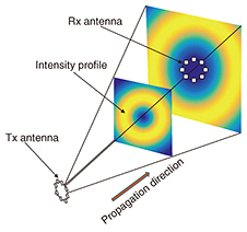
Under the free-space propagation or AWGN (additive white Gaussian noise) channel, the intensity and phase of the received signals at a certain location can be analytically obtained by Eq. (1) with parameters consisting of the radius (D) of the Tx UCA, wavelength (λ), and the Lth order Bessel function of the first kind (JL(·)). 2.4 ChallengesThis subsection highlights three major issues that have to be resolved in order to fully exploit the potential of OAM multiplexing. These issues are as follows. (1) Beam divergence Beams carrying OAM modes diverge along with their propagation as shown in Fig. 3. Other than OAM mode 0, the locations of the first Rx peak intensities of OAM modes diverge as the propagation distance increases. It may be considered that various beam-forming technologies can generate a sharp non-OAM carrying beam of which the divergence is not significant. However, the divergence of OAM carrying beams is determined by the Tx UCA radius and wavelength. It is therefore necessary to increase the physical size of the Tx UCA or to use a higher frequency in order to reduce the divergence of OAM carrying beams. Since both the Tx antenna size and frequency band are usually not tunable design factors, we leave this issue as an open problem while suggesting that the Tx antenna size be set as large as the physical environment allows.
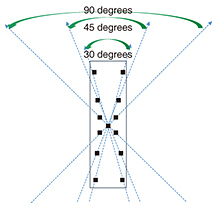
(2) Mode-dependent performance degradation The beam that carries different OAM modes yields different locations of the peak intensities. This non-identical peak Rx intensity results in mode-dependent performance degradation in accordance with the location of the Rx antenna. In addition, the required Rx antenna size to capture the peak Rx power becomes larger as the number of OAM modes increases. If the Rx antenna size is limited to a certain size, some OAM modes might not have the peak Rx power. Correspondingly, the performance degradation for higher OAM modes becomes more severe. We propose a novel Rx antenna design to resolve the issues above. 3. Proposed Rx antenna design and OAM beam separationIn this section, we introduce the proposed antenna design and discuss the issue of beam separation. 3.1 Rx antenna designIn view of the distinct beam propagation and divergence among OAM modes, it may be a good approach to put the Rx antenna for each OAM mode at its optimum or near-optimum location. For example, the use of many concentric Rx UCAs that capture OAM modes at their high Rx SNR region may lessen the beam divergence problem and mode-dependent performance degradation. In such concentric Rx UCA cases, the outer UCA is generally used for the reception of a higher OAM mode. Since the UCA antenna radius increases by the power of two in such cases, a spacious antenna is necessary to capture the higher OAM mode signals in this approach. To provide a practical solution that allows higher OAM mode signals to be received at a high Rx SNR while maintaining a reasonable antenna size, we present a simple but practical Rx antenna design and corresponding beam separation method. Our idea is based on the fact that there are specific location sets of which phase differences are 90 or 180 degrees. Since such specific location sets depend not on the Euclidean distance but on the angle conditions that will be explained later, these specific location sets are invariant in terms of the distance between Tx and Rx. This provides the flexibility in the system design. The concept of the proposed Rx antenna for concurrent transmission of seven OAM modes, including OAM modes –3, –2, –1, 0, 1, 2, and 3, is illustrated in Fig. 4. We use a four-antenna-element set to receive a pair of OAM modes of which the absolute values are identical and the signs differ from each other, for example, OAM modes 1 and –1. We also use an antenna at the center for OAM mode 0. In Fig. 4, the outermost, middle, and innermost four-antenna-element sets are respectively for OAM modes 3 and –3, 2 and –2, and 1 and –1. Four antenna elements in each set are located equidistant from the center and form an ‘X’ type configuration. The angles of the two upper antenna elements of each set are respectively 30, 45, and 90 degrees. The angles of the two lower antenna elements of each set are the same as those of the upper ones. Note that such angles become narrower as the number of OAM modes increases. Therefore, in contrast to the UCA case, the necessary area to capture the higher OAM modes does not increase by the power of two in its radius.
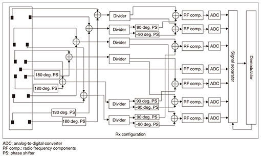
3.2 OAM beam separationWith the presented Rx antenna configuration, OAM beams are separated by analog cancellation followed by digital cancellation. We explain the details on the beam separation, which consist of the following three steps, referring to Fig. 5.
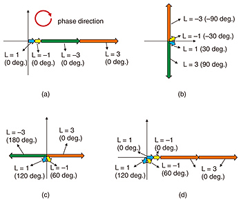
(1) Step 1) analog separation of odd and even OAM modes Diagonally located antenna elements in each four-antenna-element set are combined by either an equal-phase or a reverse-phase combination using 2-to-1 analog combiners. Before these combinations, in the four-antenna-element sets installed for odd OAM modes, the two antenna elements at the bottom are first inserted into the 180-degree phase shifters as shown in Fig. 5. With these equal-phase or reverse-phase combinations, the combined outputs can only bear either an odd or even OAM mode. (2) Step 2) analog extraction of each OAM mode In this step, we begin by explaining an example of the extraction of OAM modes –3 and 3. A conceptual example to extract OAM mode 3 is shown in Fig. 6. Two reverse-phase combined outputs from the outermost four-antenna-element set contain only odd OAM modes (i.e., OAM mode –3, –1, 1, and 3) while even OAM mode signals are canceled out.
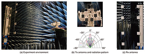
Each of the two combined outputs is again divided into two signals by a 1-to-2 divider. One output of the two dividers is inserted into the 90 and –90 degree phase shifters. The outputs of these phase shifters are respectively combined again with the outputs of the other two dividers. These combined signals respectively yield OAM modes –3 and 3 containing some interference from OAM modes –1 and 1. The interference is resolved by digital processing in step 3. OAM modes –1 and 1, and –2 and 2 are similarly extracted using two equal-phase combined outputs from the middle and innermost four-antenna-element sets. Extraction of OAM mode 0 is directly obtained from the antenna element at the center since all OAM modes disappear other than OAM mode 0 at the center. (3) Step 3) digital pruning of each OAM mode Each of the OAM mode signals extracted in the previous step is further pruned by digital signal processing such as successive interference cancellation or multiple-input multiple-output equalization. This step can be skipped when the residual interference after step 2 is negligible, or it can be intentionally skipped to reduce the complexity. 4. Evaluation: Proof of concept experimentsWe conducted proof of concept experiments to examine the feasibility of OAM multiplexing. First, beams carrying OAM modes were generated using an unmodulated signal at 5.2 GHz. Their propagation was also investigated. Second, wireless communication experiments using quadrature phase shift keying (QPSK) and 16-QAM modulated signals at the same frequency band were conducted using our proposed antenna. Our experimental environment, Tx antenna and its radiation pattern, and the proposed Rx antenna are shown in Fig. 7.
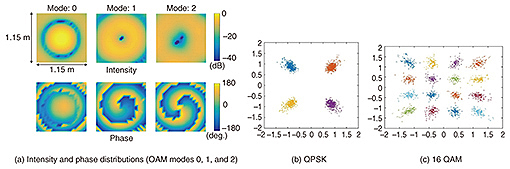
4.1 OAM beam generation and propagation experimentsThree beams respectively carrying OAM modes 0, 1, and 2 were generated using a single Tx UCA at different times. The results of measuring intensity and phase distributions are shown in Fig. 8(a). The figure shows the average intensity distribution normalized to the peak intensity of OAM mode 0 and the phase distribution in terms of the distance from the Rx antenna center. We confirmed from the measurement results that the experimental generated OAM beam propagation patterns were in good agreement with theory. Precisely, an unmodulated signal at 5.2 GHz was generated and fed into a 1-to-8 divider. The divider’s eight outputs were then respectively connected to eight tunable phase shifters. Each tunable phase shifter was connected to the antenna elements of the Tx UCA. We set the phases of the tunable phase shifters in order to independently generate beams carrying OAM modes. For example, we set the phases from 0 degrees to 315 degrees by increasing them in 45-degree increments to generate OAM mode 1. This yielded 360 degrees of phase rotation. To capture the intensity and phase distributions at the Rx plane, we used a horn Rx antenna and a moving positioner. While transmitting the generated OAM beam, we recorded the intensity and phase distribution at two-dimensional grids of the Rx plane. Our experimental setup in the shielding room is shown in Fig. 7(a), and the Tx UCA (top) and its radiation pattern (bottom) are in Fig. 7(b). Note that we conducted these experiments using a horn Rx antenna and a moving positioner. The distance between the Tx UCA and the Rx horn antenna was around 235 cm (40.7 λ), and the diameter of the Tx UCA was around 11.54 cm (2 λ). The positioner was moved over a 21 × 21 square grid. One span of the grid was 5.77 cm (1 λ), and the measured area at the Rx plane covered around 115.38 cm × 115.38 cm. The center of the grid was set to be the peak intensity spot for OAM mode 0, while it was set to be the null points for OAM modes 1 and 2. 4.2 Modulated signal transmission using OAM beamsHere, we describe the results obtained in a wireless communication experiment using modulated signals. Except for the Rx antenna, the experimental environment was the same as that used in previous experiments. Instead of using a horn antenna, we used our proposed antenna shown in Fig. 7(c). The width and height of the Rx antenna were respectively 29 cm and 70 cm. QPSK and 16-QAM modulations were used for both uncoded and coded (1/2 rate low-density parity check (LDPC)) cases. Orthogonal frequency division multiplexing was carried out with 64 subcarriers over a 20-MHz signal bandwidth. Of the 64 subcarriers, 16 were used. Due to the practical limitations of the experimental setup, this experiment was conducted using a single stream while varying the OAM modes among –2, –1, 0, 1, and 2. The OAM multiplexing was evaluated by combining these single stream signals by offline processing. The constellation maps of QPSK and 16-QAM signals obtained from a single stream are shown respectively in Figs. 8(b) and (c). Their error vector magnitude values were respectively 14.18% and 13.5% with OAM mode 1, and 14.3% and 15.65% with OAM mode 2. Through off-line combining of the received signals of three single streams (OAM modes 0, 1, and 2) that were obtained by analog extraction, we confirmed that a bit error rate less than 0.001 is feasible with LDPC coding (rate 1/2). More enhanced performance is expected when digital pruning is further applied. These results validate the feasibility of wireless transmission by OAM multiplexing.
5. Conclusion and future directionsWe introduced ways of achieving high order wireless transmission using OAM multiplexing. We also reviewed the current literature on this topic and identified two major issues. To resolve these issues, we proposed a simple but novel Rx antenna and corresponding mode separation methods. We validated the effectiveness of the proposed methods through proof of concept experiments. Many issues still remain to be addressed. For example, although in our work we did not explicitly utilize the fact that nulls of each OAM mode appear at different locations, this gives rise to other possibilities to be explored such as OAM specific spatial channel coding. Considering various aspects, from the vision of future wireless technologies to practical configurations, we are making efforts to achieve our goals that enable Tbit/s wireless transmission. References
|
|||||||||||||||||||