|
|||||||||
|
|
|||||||||
|
Practical Field Information about Telecommunication Technologies Vol. 17, No. 6, pp. 53–57, June 2019. https://doi.org/10.53829/ntr201906pf1 Examples of Wireless LAN Problems Caused by IP Packets and Wireless Encryption SchemeAbstractAs wireless local area network (LAN) communication becomes more popular, the number of failures is increasing and the causes of failure are becoming more diverse. This article introduces two cases concerning problems with wireless LAN caused by IP (Internet protocol) packets and a wireless encryption scheme. This is the fifty-second article in a series on telecommunication technologies. Keywords: wireless LAN, IP packets, WPA encryption  1. IntroductionThe spread of mobile terminals (smartphones, laptop computers, tablets, etc.) equipped with a wireless local area network (LAN) function has led to the installation of wireless LAN access points (APs) in various locations regardless of whether the AP is indoors or outdoors. Thus, an environment in which various locations can be connected to the Internet is being established. NTT EAST also offers a public wireless LAN environment as a solution called Town Wi-Fi [1]. As the Internet-connection environment is improved, wireless LANs are also adopting standards for higher communication speeds. The IEEE* 802.11ax standard—for communication speeds of up to 9.6 Gbit/s—is currently being formulated. Moreover, a multitude of vendors sell smartphones and tablet devices that support wireless LAN communication. In addition to the conventional Internet communication using a personal computer, the usage patterns of users, such as making calls with a smartphone via a wireless LAN, are becoming more diverse. Under these circumstances, as wireless LAN communication becomes more diversified, the number of failures is increasing—not only failures caused by radio waves (such as insufficient received signal strength) but also those caused by Internet protocol (IP) packets and wireless encryption schemes. Accordingly, it is necessary to establish measures for multifaceted failure response and prompt recovery. In this report, two cases are introduced concerning problems with wireless LAN caused by IP packets and a wireless encryption scheme that were handled by the Technical Assistance and Support Center.
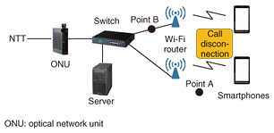
2. Case 1This case involved an investigation of the cause of call disconnections and the failure of Wi-Fi systems connected to a FLET’S Hikari optical line. 2.1 OverviewWe were notified that calls on specific terminals were constantly being disconnected at a customer’s site. The site was configured with a Session Initiation Protocol (SIP) server, Wi-Fi routers, and other devices connected to a FLET’S Hikari optical line in a manner enabling communication by smartphones via Wi-Fi (Fig. 1).
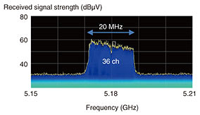
Our field maintenance department tested the optical line to confirm it was operating normally and replaced the Wi-Fi router. The call disconnections were not resolved, however, so the Technical Assistance and Support Center was asked to investigate the cause of the failure. 2.2 Investigation of cause and results of investigationFirst, a call test was conducted using two terminals: one made by company A (vendor recommended) and one made by company B (not vendor recommended) that was affected by call disconnections while the customer was using it. It was confirmed that a disconnection occurred during extension calls between the company-B-made terminals. To identify the cause of the failure (disconnection), we investigated the radio-wave environment and the communication protocol between the Wi-Fi router and the SIP server. (1) Radio-wave environment The radio-wave environment near the AP (point A in Fig. 1) was measured using a spectrum analyzer (Tektronix RSA 6104A). The measurement results revealed that the received signal strength was sufficiently high at 60 dBμV (with the minimum reception sensitivity at 27 dBμV), and no disturbance waves or interference waves were found to be present (Fig. 2).
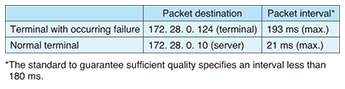
(2) Communication protocol Using a packet capture tool (Wireshark), we captured packets between the Wi-Fi router and the server (point B in Fig. 1). The results of the packet capture test are listed in Table 1. If the terminal can communicate normally, the packets are sent to the server only once. On the contrary, if the terminal suffers a failure, packets are sent directly to other terminals without going through the server. The maximum packet interval was 21 ms in a normal case and 193 ms in the event of the failure. In other words, in the failure case, it exceeded 180 ms, which is the standard for guaranteeing quality.
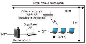
2.3 Estimation of cause of failure and responseThe results of the above-described investigation indicated that the disconnected calls occurred during extension calls using the company-B-made terminal, namely, the one not recommended by the vendor. The reason for this finding is explained as follows. The SIP server has a buffer that absorbs packet-interval fluctuations, so communication via the server is normal. In the case of the terminal with the failure, packets are sent directly to the other terminal (i.e., without going through the server). We thus presumed that the failure occurred because the packet-interval fluctuation could not be absorbed. The failure can therefore be resolved by using only terminals recommended by the vendor. 3. Case 2The next case involved an investigation into the cause of a failure in Giga Raku Wi-Fi communication in the press room of an event venue. 3.1 OverviewIn this case, a constant communication failure (disconnection and decrease in throughput) was occurring in the Giga Raku Wi-Fi service installed in the press room at an event venue. Although the APs were rebooted and other measures were tried, the failure was not resolved; consequently, we were asked to investigate the cause of the failure and to take measures to fix it. The customer was using laptop computers connected to a Giga Raku Wi-Fi AP (high-end-type made by company C) under an ONU (optical network unit) integrated router. Another company’s Wi-Fi AP was set up in the center of the press room (Fig. 3).
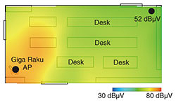
3.2 Investigation of cause and results of investigationFirst, a wireless LAN tester (a product developed by the Technical Assistance and Support Center [2]) was used to confirm the failure. After the tester with the Giga Raku Wi-Fi AP (channel 1) was connected and throughput was measured, it was confirmed that a disconnection occurred during communication. Next, we conducted investigations on the Wi-Fi radio-wave received signal strength, the radio-wave environment, and the communication protocol between APs and terminals to identify the cause of the failure. (1) Wi-Fi radio-wave received signal strength Received signal strength in the room was measured by using the received signal strength-distribution map-creation function of the wireless LAN tester. The results of that measurement indicated that the received signal strength was 52 dBμV (with a minimum reception sensitivity of 27 dBμV) even at the lowest location, which indicates that the received signal strength was sufficient anywhere in the room (Fig. 4).
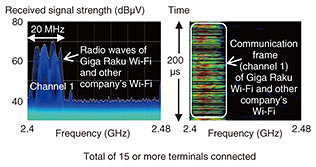
(2) Radio-wave environment A spectrum analyzer (Tektronix RSA6104A) was used to measure the radio-wave environment at the location of the failure (point A in Fig. 3). According to the results of that measurement, although another Wi-Fi radio wave (from the other company’s Wi-Fi AP) was recognized on the same channel as the radio wave from the Giga Raku Wi-Fi AP (channel 1), no other disturbances were discovered (Fig. 5).
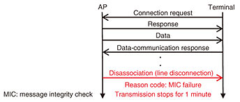
(3) Communication protocol between APs and terminals A Wi-Fi failure-analysis tool (Air Magnet) was used to measure the protocol for communication between the APs and terminals. According to the results of that measurement, a so-called disassociation packet was sent from the AP to the terminal to confirm that a disconnection had occurred (Fig. 6). This disconnection was due to a message integrity check (MIC) failure. This kind of communication disconnection occurs when there is a tampering-detection-code error in the cryptographic frame used in Wi-Fi Protected Access (WPA) encryption.
3.3 Cause of failure and countermeasureThe results of these investigations suggest the cause of the disconnection and the resulting decrease in throughput were as follows. (1) Communication disconnection The Wi-Fi communication is disabled (stopped) for one minute on detection of an MIC failure in WPA encryption. WPA is not recommended because of its cryptographic vulnerabilities [3]. Accordingly, changing the setting to allow only WPA2 encryption is considered a potential measure to eliminate the failure. (2) Decrease in throughput Since both Giga Raku Wi-Fi and Wi-Fi of other companies use channel 1, throughput is reduced when many terminals communicate on channel 1. We expect that changing the channel of the Giga Raku Wi-Fi from channel 1 (automatic setting) to channel 11 (fixed setting) will improve throughput. When we actually changed the channel in that manner, we found that throughput was improved by approximately 30 Mbit/s. 4. Concluding remarksIn this report, two example cases concerning problems with wireless LAN tackled by the Technical Assistance and Support Center were introduced. These examples demonstrate that the number of failures is increasing, not only failures caused by radio waves (such as insufficient received signal strength) but also those caused by, for example, communication protocols and communication packets. In the EMC Engineering Group of the Technical Assistance and Support Center, to quickly resolve noise problems (such as conduction and radiation) and contribute to the smooth provision of communication services, we will continue to actively engage in technical collaboration, technology development, and technology dissemination activities through technology seminars. References
Trademark notesAll brand names, product names, and company/organization names that appear in this article are trademarks or registered trademarks of their respective owners. |
|||||||||