|
|||||||||
|
|
|||||||||
       |
Practical Field Information about Telecommunication Technologies Vol. 18, No. 12, pp. 109–113, Dec. 2020. https://doi.org/10.53829/ntr202012pf1 Manual for Assisting with Troubleshooting in PHS Digital Cordless Telephone SystemsAbstractThis article introduces a manual for assisting with troubleshooting in digital cordless telephone systems. The Technical Assistance and Support Center, NTT EAST, published this manual to help service personnel in the field. This is the sixty-first article in a series on telecommunication technologies. Keywords: digital cordless telephone, PHS, DCL, DECT
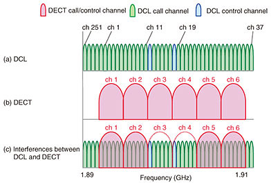
1. IntroductionDigital cordless telephones based on the personal handy-phone system (PHS) (hereafter, called the DCL) enable voice communications between a master unit called a cell station (CS) and a slave unit called a personal station (PS) via digital wireless communications. The DCL is widely used by business customers and consumers in Japan. On the other hand, the digital enhanced cordless telecommunication system (DECT), which uses the same frequency band as the DCL (i.e., 1.9-GHz band), has come into wide use as digital cordless telephones and intercoms for consumers. This indicates that these two wireless systems, the DCL and DECT, co-exist in the same frequency band, and the number of technical consultations concerning problem cases has been increasing. The Technical Assistance and Support Center (TASC) of NTT EAST has published a manual to provide efficient and simple troubleshooting methods for digital cordless telephones for maintenance personnel on site. This manual presents simple techniques for evaluating wireless communication conditions without the need for dedicated measurement instruments, such as a spectrum analyzer or wireless protocol analyzer. It also provides a simple procedure on how to determine the cause of a problem. 2. Features of DCL and DECTThe DCL [1] and DECT [2], which both use the 1.9-GHz band, have the following features (their frequency allocations are illustrated in Fig. 1 [3]).
3. DCL problem-isolation process flowTable 1 summarizes the problems, estimated causes, and their countermeasures concerning the DCL categorized using the data gathered from cases we have dealt with thus far. The problems concerning the DCL claimed by customers are roughly divided into (i) “call is breaking up,” (ii) “no sound,” and (iii) “intermittent sound.” There are three factors that lead to such problems: (a) handover, (b) insufficient received signal strength, and (c) interference with other wireless systems. The following are examples of such problems:
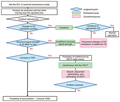
Let us consider a case in which multiple CSs are installed in an area and a customer holds a PS that is registered with one of those CSs. The PS monitors radio waves from the registered CS and receives radio waves from other unregistered CSs. It switches its registration to another CS when the received signal strength of the radio waves becomes weaker due to the customer moving around. This operation is called handover and a time lag of about one second occurs by switching CSs, which is a normal operation of wireless communication. However, some customers claim that a problem occurred and say, “the call was interrupted” or “no sound.” In another case in which some CSs are closely located and their reach overlaps, a PS could attempt to keep receiving radio waves from the registered CS even when the received signal strength decreases. In this case, the handover does not work well. This may increase errors and lead to deterioration in call quality. To solve these problems, the terminal-maintenance-mode of the PS enables easy checking of radio communication on site. This mode enables checking of the received signal strength (level), identifier (ID) of the registered CS (BS-ID), and frame error rate (FER). Various causes of a problem can be isolated by comparing these values before and after the problem occurred. A troubleshooting flow chart is shown in Fig. 2. Before troubleshooting, the area where the problem occurred is estimated through consultations with the customers, and reproduction of the claimed problem is attempted. After the problem is observed, the PS is set to the terminal-maintenance mode, and three parameters are evaluated. First, the ID of the currently registered CS (displayed on the PS) is checked, and the PS is moved to where the problem occurred. The ID of the registered CS before handover is compared with that after the handover. If the CS selection is appropriate, the received signal strength is then checked. The DSL determines if there is insufficient received signal strength and executes handover when the received signal strength is 30 dBμV or less. Around this limit of 30 dBμV, errors sometimes occur due to quality deterioration of the call. If both CS selection and received signal strength are appropriate, the FER is finally evaluated. If the FER increased (approximately 24 or higher), the DECT or other wireless systems could be interfering with the DCL.
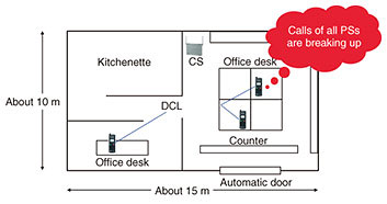
By investigating a case according to the procedure in the manual using the terminal-maintenance mode, the cause of the reported problem could be determined and the primary countermeasure could be applied on site. 4. Example case of problem4.1 Details of problemA customer using a DCL of the αA1 key telephone system reported that “calls in the store are breaking up.” The customer’s equipment is illustrated in Fig. 3. A CS is installed near the center of the first floor in the store.
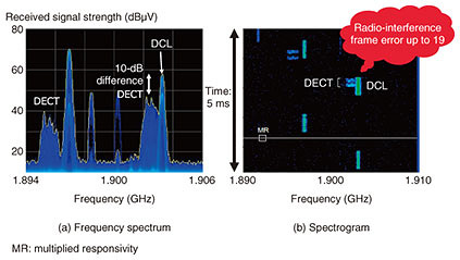
4.2 Investigation and resultsThe PSs were set to the terminal-maintenance mode on the first floor of the store, and the investigation was conducted according to the flow chart shown in Fig. 2. In this case, the handover was not executed since there was only one CS. The investigation was therefore started by checking the received signal strength. The strength in the customer’s store was 40 dBμV or higher, so there was no issue with that. Then the FER was checked, revealing that the FER increased in a specific place in the store. The results of this investigation following the manual indicate that radio waves of other wireless systems may have been interfering with the DCL radio waves. However, no equipment using other wireless systems was found in the store. To evaluate the electromagnetic environment in more detail, the radio-wave spectrum was measured using a spectrum analyzer where the problem occurred. The results of that measurement are illustrated in Fig. 4. The frequency spectrum and spectrogram (i.e., time change of the spectrum) when a call was interrupted are shown in Figs. 4(a) and (b), respectively. From Fig. 4(a), we can see the DCL signals exist in the frequency band of the DECT. Similarly, the spectrogram revealed that the DCL and DECT signals overlap. These results indicate that the reported problem was due to interference between the DCL and DECT radio waves.
4.3 Estimation of causeAs a result of investigating the electromagnetic environment including the area outside the customer’s store, we found that DECT terminals were being used in an adjacent store and the radio waves from those terminals were interfering with other terminals in the customer’s store. The DECT can usually prevent interference with DCL radio waves by detecting the usage status of radio waves with carrier sensing and switching channels depending on the results. However, in the case of this customer’s environment, interference prevention would not work well because the terminals in the two stores were far apart. 4.4 CountermeasureWe confirmed that wireless signals including those from the adjacent store are transmitted by less than 12 slots in the customer’s area and replaced the customer’s PSs, i.e., A1-DCL-PS terminals (DCL), with A1-DECT-PSSET terminals (DECT), which can be adapted for up to 12 slots (12 terminals) in the same frequency band. 5. Current status of DCL problemsThe number of technical consultations concerning the DCL using the 1.9-GHz band is gradually increasing; we had 159 cases in 2018. The main reasons of the consultations are “the call is breaking up,” “cannot make a call,” etc., and analysis of our on-site investigation revealed that most causes of those problems are either interference with the DECT or handover. Moreover, some customers using the DCL often report one-second interruption caused by normal handover operation as a problem. Thus, it is important to explain that handover will occur with some interruption to customers before they start using the DCL. When a problem occurs, using the terminal-maintenance mode of PSs helps determine the problem because service personnel can determine the operating status of the PSs and radio-wave environment. Based on such information, measures that optimize the wireless environment, such as adjusting the installation position of CSs, increasing or decreasing the number of installed CSs, and adjusting their signal power can be implemented. The “DCL Troubleshooting Manual” is available for download at CyberTasc (URL: https://www.cybertasc.com/), a site for disseminating information to telecommunication construction companies (limited access and written in Japanese). 6. ConclusionThis article introduced the content of the troubleshooting manual concerning the DCL. TASC provides this manual to improve the efficiency of such troubleshooting in the field. The Network Interface Engineering Group in TASC works on solving various problems related to the network protocol, interface, signals, and so on, toward early resolution of problems on site. TASC will continue to actively engage in technical cooperation and development and disseminate its technologies through activities such as technology seminars. References
|
||||||||