|
|||||||||||||||||||||||||||||||||||||||||||||||||
|
|
|||||||||||||||||||||||||||||||||||||||||||||||||
       |
Feature Articles: NTT DOCOMO's Initiatives on 5G evolution & 6G Vol. 19, No. 11, pp. 26–34, Nov. 2021. https://doi.org/10.53829/ntr202111fa2 Research of Transparent RIS Technology toward 5G evolution & 6GAbstractThe introduction of the 5th-generation mobile communications system (5G) commercial services has begun throughout the world, and at present, research toward the further development of 5G (5G evolution) and the development of 6G as the next-generation mobile communications system is being actively pursued. In this article, we describe the intelligent radio environment (IRE), an important concept in “New Radio Network Topology” now under discussion on the road to 5G evolution & 6G. We also describe NTT DOCOMO’s initiatives toward the reconfigurable intelligent surface (RIS), an important component of IRE, and metamaterial/metasurface technologies as elemental technologies of RIS. Keywords: 5G evolution, millimeter wave, metasurface
1. IntroductionIn Japan, NTT DOCOMO launched commercial services of the 5th-generation mobile communications system (5G) in March 2020. This launch has raised expectations for the application of 5G technology to XR*1 such as virtual reality (VR), augmented reality (AR), and mixed reality (MR) and to a variety of fields as in industry/infrastructure enhancement through Internet of Things (IoT) devices [1]. Against this background, NTT DOCOMO has come to demonstrate through field experiments the potential of 5G for achieving high-speed/high-capacity, low-latency, and high-reliability communications using radio signals in the millimeter-wave*2 frequency band [2, 3]. However, it became clear through these field experiments that problems existed in the effective use of millimeter waves in radio communications of a cellular system. With millimeter waves, radio signals have a strong tendency to propagate in a straight line much like light, so their ability to wrap around shielding objects (diffraction) is small. It can therefore be said that the key to using millimeter waves in radio communications of a cellular system is determining how to expand the area covered by a base-station antenna to non-line-of-sight locations. In this article, we first present the concept of the intelligent radio environment (IRE) that is now attracting attention as a useful approach to forming coverage areas in the millimeter-wave band, an important issue in achieving 5G evolution & 6G. We then turn to NTT DOCOMO initiatives surrounding the reconfigurable intelligent surface (RIS) as key to achieving IRE and describe metamaterial*3/metasurface*4 technologies, the elemental technologies of RIS.
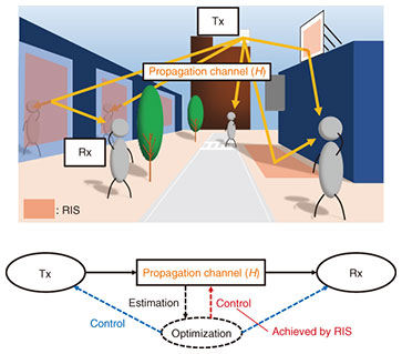
2. IRE and RIS2.1 IREResearch toward IRE has been quite active in recent years with the aim of adaptively and dynamically controlling the radio environment to achieve non-line-of-sight coverage in the millimeter-wave band [4]. In a white paper [1] issued by NTT DOCOMO toward 6G, a New Radio Network Topology was proposed to increase the number of connection paths to the network including discussions on controlling the radio environment. In this regard, it is difficult to solve the problem of radio waves being blocked by shielding objects simply through the evolution of transmitter/receiver technology, so the need is felt for constructing a new radio network system. Against this background, means of achieving a dramatic jump in radio network performance are being vigorously studied by breaking with the traditional assumption that the radio environment is uncontrollable and treating it instead as a controllable entity. This type of approach has come to be called the intelligent radio environment (IRE) or smart radio environment (SRE) to emphasize its conceptual difference with the conventional radio network system. A conceptual diagram of IRE is shown in Fig. 1. Given an environment with shielding objects, IRE can secure propagation routes that make detours around shielding objects by optimally controlling not only the transmitter (Tx) and receiver (Rx) but the propagation channel*5 (H) as well.
2.2 RISRIS is essential technology for achieving IRE described above. A RIS consists of multiple elements that scatter electromagnetic waves. Metamaterial/metasurface technologies that can design and control the distribution of these scattering characteristics are commonly used to achieve RIS. A metasurface has a thin flat shape, and depending on the base materials selected, it is even possible to manufacture one in the shape of a flexible sheet that can be installed along the side of a structure. This makes it possible to control the scattering characteristics of radio waves while maintaining the shape of existing structures. Within the Tx – propagation channel – Rx sequence, this means controlling the propagation channel. In general, RIS can be expected to adaptively control the radio environment by periodically repeating the following operations.
Various approaches to implementing this procedure have been researched. Furthermore, as a term referring to the same technology as RIS, there is the large intelligent surface (LIS), and there is also the intelligent reflecting surface (IRS) that focuses only on controlling reflected waves. 2.2.1 Effect of RIS sizeGiven a non-line-of-sight situation between a base station (BS) and mobile station (MS) in which a reflector or repeater*6 is used to relay radio signals (BS – reflector/repeater – MS), path loss*7 occurs two times, once in the BS – reflector/repeater interval and again in the reflector/repeater – MS interval. The drop in energy density of a wave due to propagation is larger at positions closer to the wave source. Thus, even for the same total path length, path loss is generally greater for the BS – reflector/repeater – MS path than the BS – MS path leading to a drop in received power. This tendency of path loss to increase applies to RIS as well. Path loss via RIS is affected by surface size the same as an ordinary metal reflector, but in the case of RIS, path loss depends not only on size but also on the method of phase control. With this in mind, we first examine how RIS size affects received power and introduce the results of analyzing the relationship between path loss that occurs twice via RIS (hereinafter referred to as “double path loss”) and path loss of a direct wave for the same path length [5]. In this analysis, calculations were performed for the following two cases.
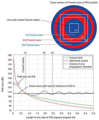
The relationship between RIS size and path loss for each of the above paths in the 28 GHz band as determined by computer simulation is shown in Fig. 2. In this computation, the RIS is square-shaped, reflectivity is 100%, and BS – RIS – MS is assumed to lie along a straight line. In actuality, RIS can be expected to lie at an angle with respect to BS/MS and not along a straight line, in which case its effective area decreases by the amount of that angle.
Focusing our attention on controlling only the propagation direction with no special phase control (blue line in Fig. 2) and considering the case that RIS is smaller than a certain size ((1) in the figure), double path loss via RIS is considerably greater than path loss of a direct wave for the same path length. However, as RIS size becomes larger than that of (1), it can be seen that double path loss asymptotically approaches path loss of a direct wave for the same path length. Furthermore, though described in more detail later, double path loss when subjecting RIS to optimized control to maximize received power at MS takes on the values shown by the red line in the figure. Now, by analytically determining the RIS size for which this optimally controlled double path loss is equal to direct-wave path loss at (1) in the figure, the length of one side of this RIS turns out to be the Fresnel radius*8. It can also be seen from the figure that, even without optimized control of RIS, the RIS size at which path loss is equal to that of the direct wave nearly agrees with the Fresnel radius, and if the RIS becomes larger than that size, an amount of power equivalent to that of the direct wave for the same path length can be received (blue line in the figure). In addition, the reason for the alternating increase/decrease in double path loss as it asymptotically approaches path loss of the direct wave with increase in RIS size is the canceling out of signals via the odd-numbered and even-numbered Fresnel zones*9 at the receiving point. 2.2.2 Effect of phase control by RISOn breaking down the BS – RIS – MS propagation path by each element making up the RIS, we consider that the received power of the BS – RIS – MS path can be maximized by performing RIS phase control so that the waves on each path have the same phase at the receiving point (red line in Fig. 2). If optimized control is performed in this way, the received power ends up having a positive correlation with RIS size instead of converging to the value of the direct wave path. Furthermore, if RIS size should be less than the Fresnel radius, practically no difference can be observed between conventional control of only the propagation direction (blue line in the figure) and optimized phase control, so direction-only control is sufficient in this interval. When performing optimized control of a RIS from the viewpoint of received power, the amount of phase change in each element of the RIS must be set to an optimal value as described above. This, however, may complicate the control process. To simplify this process, we introduce a technique that can significantly improve received power by adding phase compensation consisting of only two values—0 and π (rad)—to direction-only control. As shown in Fig. 2 for the case of direction-only control, path loss increases and decreases repeatedly as RIS size becomes larger. Here, received power can be significantly improved by shifting the wave phase by π (rad) via the even-numbered Fresnel zones, the cause of this increase-decrease behavior (green line in the figure). This technique (hereinafter referred to as “Fresnel shift”) can improve received power depending on RIS size the same as optimized control even for users positioned at any distance. Details of this technique are provided in another paper [5].
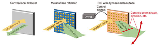
3. Study of metasurface technology toward transparent RISAs described above, metamaterial/metasurface technologies are commonly used to achieve RIS. A metamaterial features a periodic arrangement of structures each sufficiently smaller than the wavelength of an electromagnetic wave. This artificial periodic structure can, in effect, behave as a material having a negative refractive index, so it can be used to obtain characteristics that cannot be achieved by ordinary material. As a consequence, metamaterial technology has been vigorously researched since 2000 [6]. Demonstrations of metamaterial technology were initially conducted in the microwave band (5 GHz), but studies in the millimeter-wave and terahertz-wave*10 bands have been active since 2010 [7]. This is thought to be due to various factors. For example, the elemental structures making up metamaterial are of a size on the order of mm – µm that can be easily fabricated by existing manufacturing processes. In addition, these are frequency bands for which the electrical resistance of metals can be nearly ignored, the same as for frequency bands used in conventional mobile communications. Moreover, while a metamaterial is a three-dimensional artificial periodic structure, a two-dimensional artificial periodic structure is often called a metasurface. Controlling the reflection phase distribution on the metasurface enables the propagation of reflected waves to be controlled (Fig. 3).
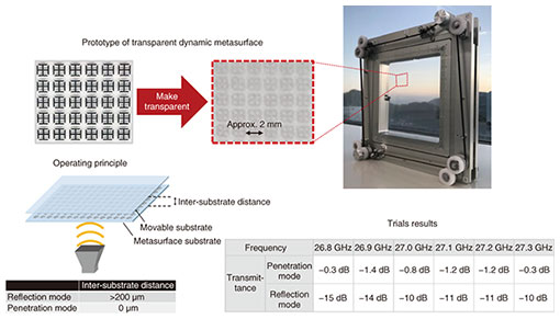
At present, metamaterial/metasurface technologies are described as important technologies in 6G-oriented white papers issued by a variety of research institutions. The following describes NTT DOCOMO initiatives surrounding metasurface technology toward the practical implementation of RIS. 3.1 Transparent dynamic metasurfaceIn 2018, researchers at NTT DOCOMO began studying static metasurface reflectors that do not provide dynamic control with an eye to expanding millimeter-wave coverage to non-line-of-sight locations [8]. However, for the metasurface reflector studied here, it was necessary to design a reflection phase distribution according to incident/reflected angles calculated from the installation location, base station position, and location targeted for reception. Another problem was that the area behind the reflector became a new non-line-of-sight location. It was also desirable that the reflector has a design or look that blends in with the city landscape. In response to the above issues, we have been developing and studying a “transparent dynamic metasurface” in cooperation with AGC Inc. as a RIS prototype that can dynamically control the reflection and penetration of radio waves while maintaining high transparency (Fig. 4) [9]. The metasurface substrate is covered with a transparent glass substrate to make it transparent, and moving the glass substrate slightly enables dynamic control of radio waves in three modes: full penetration of incident waves, partial penetration and partial reflection of radio waves, and reflection of all radio waves.
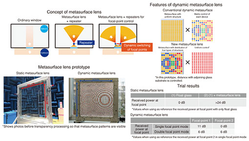
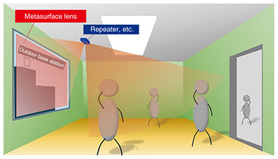
The mainstream method for achieving dynamic metamaterials and metasurfaces in the past was to use semiconductors to control the resistance and electrical-capacitance components of metallic patterns. Our new method for achieving transparent dynamic metasurfaces is superior to the conventional technique using semiconductor devices by virtue of “enabling dynamic control while maintaining transparency” and “making it easy to enlarge the substrate.” Use of a transparent dynamic metasurface also minimizes impact on the surrounding environment and on existing designs on installation. A trial performed to assess the performance of the prototype RIS showed that it could achieve transmittance of approximately –1.4 dB or greater in penetration mode and approximately –10 dB or less in reflection mode (calculated as reflectivity of –1 dB or greater) in 400 MHz or higher bands (Fig. 4). Going forward, we plan to study further functional enhancements such as functions for controlling penetration/reflection directions with the aim of achieving a practical transparent RIS. 3.2 Making windows into radio-wave lenses by transparent metasurface lensCompared with radio waves in the frequency bands currently used in LTE (Long Term Evolution) and the Sub-6*11 band, radio waves in the millimeter-wave band have high straight-line propagation properties and attenuate easily. For this reason, radio waves emitted from outdoor base station antennas attenuate before arriving at the glass window of a building, and in addition, attenuated and weak radio waves penetrate an indoor space without spreading out. It is therefore difficult to make such an indoor space into a coverage area using outdoor base station antennas. In response to these issues, we developed in cooperation with AGC Inc. a “transparent metasurface lens” that can guide millimeter waves passing through a glass window to a specific indoor location (referred to below as a “focal point”). This is a film-like lens that can be affixed to a glass window from the indoor side [10, 11]. Focusing weak radio waves that pass through the entire surface of a glass window at a focal point in this way can increase power, so installing an area improvement tool such as a repeater, reflector*12, or RIS at the focal point position should make it possible to extend area coverage from outdoor base station antennas to the inside of a building (Figs. 5 and 6). In a trial using this metasurface lens, we found that the received power at the focal point could be improved by 24 dB or more compared with the case of an ordinary transparent glass.
We also tested a function for dynamically controlling focal points. In this regard, the conventional approach to controlling the penetration/reflection direction of radio waves was to configure a metasurface with a uniform arrangement of identical devices and to apply different control signals to each device. In contrast, our new dynamic metasurface lens appropriately arranges devices with four different types of structures so that focal point positions can be switched (presently between a single focal point and two focal points) even when applying the same control signal to all devices (Fig. 5). In single focal point mode, the received power at focal-point 1 was shown to be 11 dB higher than that at focal-point 2 indicating that only focal-point 1 was functioning as a focal point. Meanwhile, in double focal point mode, received power at both focal-point 1 and focal-point 2 was shown to be 6 dB higher than that at focal-point 2 in single focal point mode indicating the formation of two focal points. Simplifying the control process in this way raises the possibility of dynamically controlling focal points even with a large-area metasurface lens.
4. ConclusionIn this article, we presented the concept of IRE that attempts to adaptively control the radio environment, which is deemed to be a useful approach to achieving non-line-of-sight coverage in the millimeter-wave band, an important issue in achieving 5G evolution & 6G. We also described RIS as an elemental technology of IRE and metamaterial/metasurface technologies that form the foundation of RIS. When influencing the propagation environment by a reflector or RIS of limited area, controllability increases the larger is that area with respect to that wavelength, i.e., the higher is the frequency of the propagating wave. The technology described here is expected to become a base technology for constructing coverage areas not only for 5G but also for 6G and beyond radio systems whose frequencies are expected to be even higher. Going forward, we plan to assess the effectiveness of the RIS technology described in this article in actual environments and to study the application of even higher frequencies with RIS toward 6G. This article is the reproduction of the special article published in NTT DOCOMO Technical Journal (Vol. 23, No. 2, Oct. 2021). References
Trademark notesAll company names or names of products, software, and services appearing in this article are trademarks or registered trademarks of their respective owners. |
||||||||||||||||||||||||||||||||||||||||||||||||