|
|||||||||||||||||||||||||||||||||||||||||||||||||||||||||||||||||||||
|
|
|||||||||||||||||||||||||||||||||||||||||||||||||||||||||||||||||||||
       |
Feature Articles: NTT DOCOMO's Initiatives on 5G evolution & 6G Vol. 19, No. 11, pp. 35–43, Nov. 2021. https://doi.org/10.53829/ntr202111fa3 Research on NTN Technology for 5G evolution & 6GAbstractIn the 5th-generation mobile communication system (5G) evolution & 6G, extreme coverage extension is being studied for use cases in all places including air, sea, and space. Non-terrestrial networks using geostationary satellites, low earth orbit satellites, and high-altitude platform stations are promising tools for providing high-quality communication services in areas that cannot be covered by the conventional mobile communication network. In this article, we describe these technologies and the details of a 39-GHz band airborne propagation measurement experiment performed using a small airplane at an altitude of about 3 km. Keywords: NTN, HAPS, extreme coverage extension
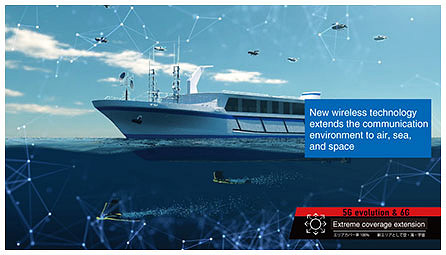
1. IntroductionWhile the 5th-generation mobile communication system (5G) is expected to be an important technology for regional development and solving regional issues, a key issue for the 5G evolution and 6G era is expected to be expanding the communication area to any place where its benefits can be enjoyed [1]. As shown in Fig. 1, NTT DOCOMO is conducting research and development aimed at achieving extreme coverage extension whereby mobile communication can be made available in all locations, including the air, sea, and space, that are not adequately covered by conventional mobile communications networks, thereby extending coverage to drones, flying cars, ships, and even space stations.
To achieve this extreme coverage extension, we are focusing on non-terrestrial network (NTN)*1 technology using satellites and high-altitude platform stations (HAPS)*2. This technology is able to provide communication coverage in mountainous and remote areas, at sea, and even in outer space by employing satellites and HAPS systems that are free of geographical restrictions. This article describes extreme coverage extension, which is one of the key issues for the realization of 5G evolution & 6G. Specifically, we describe the concept of NTN technology, which has been attracting attention as a promising approach, the use cases and technical issues of wireless system technology using HAPS, and our work on measuring the propagation of radio waves using a small aircraft.
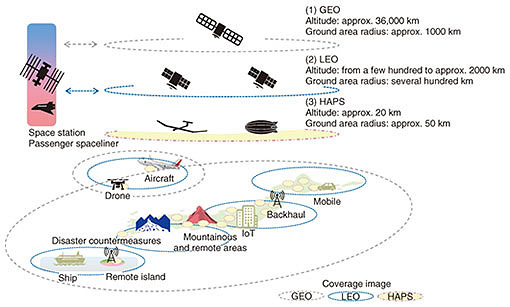
2. Extreme coverage extension and NTN technology for 5G evolution & 6GExtreme coverage extension supports use cases in any location, including air, sea, and space. This will extend coverage to users that cannot be covered by conventional mobile communication networks, including drones, flying cars, ships, and space stations. To achieve extreme coverage extension, it will be necessary to develop technologies that facilitate highly efficient long-range wireless transmission over at least several tens of kilometers. As shown in Fig. 2, by considering the use of (1) geostationary (GEO) satellites, (2) low earth orbit (LEO) satellites, and (3) HAPS, we will be able to cover mountainous and remote areas, the sea, the sky, and even outer space, and to provide communication services to these areas [2].
(1) GEO satellite A GEO satellite orbits the Earth at an altitude of about 36,000 km. Although the one-way radio wave propagation time between a GEO satellite and a ground station antenna is relatively long (about 120 ms), just three or four GEO satellites can provide the entire planet with constant coverage. Even today, GEO satellites are used to complement terrestrial networks by providing a mobile backhaul*3. Since additional network capacity will be required in the 6G era, very high throughput satellites are being studied with the aim of improving system capacity by optimizing the allocation of power and frequency across multiple beams [3]. (2) LEO satellite An LEO satellite orbits the Earth at an altitude ranging from a few hundred km to about 2000 km. Unlike a GEO satellite, it has a much lower orbit and a much smaller propagation delay (just a few ms for a one-way trip). LEO satellites are currently used for satellite mobile phone systems and satellite sensing*4. They are also expected to be used for the expansion of communication capacity through the reduction of satellite fabrication costs and the use of multiple input, multiple output (MIMO)*5 technology, and for high-capacity, low-latency backhauls in satellite constellations that form networks through cooperation between multiple satellites [4]. (3) HAPS HAPS have recently attracted renewed attention due to their ability to parked at an altitude of about 20 km in fixed locations, allowing them to provide services across terrestrial cells*6 with a radius of approximately 50 km or more [5]. Since their altitude is lower than that of LEO satellites, it is possible to achieve a one-way radio wave propagation time of about 0.1 ms, depending on the cell radius. As a result, they are considered to be an effective way of deploying services not only in regions that have been hit by natural disasters but also in many of the industrial use cases envisioned for 5G evolution & 6G. The 3rd Generation Partnership Project (3GPP) has begun studying how satellites and HAPS can be used to extend New Radio (NR)*7 to NTNs [6].
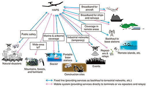
3. HAPS use cases and network configuration/control techniquesNTT DOCOMO is working on the research and development of communication methods and network architectures that can flexibly link 5G networks and other terrestrial networks with stratospheric HAPS networks [7, 8]. In addition to providing flexible support for a wide range of future use cases as envisioned in 5G evolution & 6G, this project is conducting studies aimed at the implementation of communication systems that use realistic HAPS in terms of development and operation costs. 3.1 HAPS use casesAs shown in Fig. 3, for the 5G evolution & 6G era, it is expected that various use cases will involve using HAPS to relay radio waves or emit radio waves as a base station. These use cases include fixed systems that provide services for backhaul applications, and mobile systems that provide services to terminals either directly or by via repeaters and relays. In particular, the use of broadband millimeter wave*8 radio signals is expected to enable the timely provision of high-speed, large-capacity, low-latency lines required for various applications including industry and public events, regardless of whether or not optical fibers or other wired networks are available, and in any location, including at sea, in the air, or in remote areas.
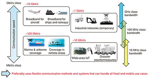
The requirements of HAPS systems can vary widely from one use case to the next. As shown in Fig. 4, different use cases require different communication speeds and different bandwidths. There is a need for flexible communication methods and systems that can support all use cases of fixed and mobile systems. For example, it is considered that the communication speed for backhaul applications to 5G base stations will have to be at least 1 Gbit/s per service link*9. Furthermore, to provide multiple simultaneous service links, the feeder link*10 will have to be capable of even faster communication speeds (several Gbit/s to several tens of Gbit/s) and must operate as stably as possible regardless of weather-related effects.
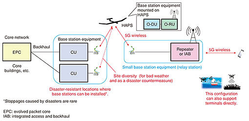
It is also necessary to flexibly control lines so that they can be adapted from normal business applications to public safety*11 applications in the event of a disaster. Current disaster countermeasures are geared towards providing basic communication services such as voice calls and short message services, but in the future, it may also be necessary to consider use cases that require faster communication speeds, such as remote control of equipment at disaster sites, video transmission, and communication via drones. For disaster countermeasures, it will also be necessary to study network configurations and control techniques that assume the ability of a system to operate even if some devices become unavailable. 3.2 Technology for network configuration and control in conjunction with 5G networks3.2.1 Classification of HAPS-mounted stationsIn the network configuration and control technology used when implementing backhauls to 5G base stations via HAPS, we are focusing on the categorization of HAPS-mounted stations. They can be roughly divided into two types: (1) relay stations, which receive signals from ground stations and relay them back to other ground stations after performing necessary processes such as frequency conversion, and (2) base stations, which are made by installing 5G network base station equipment (or at least part of it) in a HAPS. (1) Relay station type The relay type is effective when the number of on-board devices is relatively small and the size, weight, and power consumption of the HAPS-mounted station are strictly limited. (2) Base station type The base station type is formed by equipping a HAPS with an antenna device, together with many base station functions. The more of these functions it includes, the greater the amount of control that can be performed within the HAPS, making it possible to reduce the amount of feeder link information. On the other hand, installing more functions results in a station that is larger, heavier, and consumes more power. In general, implementing more of the base station functions on the ground network side has the advantages of lower development costs and ease of operation, but implementing these functions on the HAPS results in greater resilience to natural disasters. In terms of performance, a HAPS-mounted station should at least implement some functions, such as beam control when using millimeter waves. It is also necessary to comprehensively study a wide range of requirements to be considered when incorporating HAPS systems into a 5G network. These include the size, weight, and power consumption of HAPS-equipped stations, their development and operation costs, the ability of these HAPS platforms can be shared by fixed-line and mobile communication systems, and their ability to cooperate with GEO/LEO satellites. 3.2.2 Examples of network configuration in conjunction with the 5G networkAn example of a HAPS base station in a network configuration linked to the 5G network is shown in Fig. 5. Here, the distributed unit (DU)*12 and radio unit (RU)*13 of the 5G base station are mounted on the HAPS in accordance with Open RAN (O-RAN)*14 Alliance specifications [9]. In this configuration, availability is ensured by installing a centralized unit (CU)*15 at a disaster-resistant point on the ground. Information received by the HAPS from the CU in the feeder link is transmitted via 5G radio to a small terrestrial base station device (relay station) in the service link, thereby enabling the use of portable 5G base stations without having to use a wired backhaul. In this configuration, it is also possible to provide direct communication from the HAPS to 5G terminals without the need for intervening relay stations. As a further extension, site diversity*16 can be implemented by using multiple CUs on the ground side to reduce the impact of bad weather and natural disasters, and mobility support*17 can be implemented by switching the communication target to a different HAPS when the terminal moves from one communication area to another.
In addition to the configuration shown in Fig. 5, we are also considering other promising configurations: one in which a HAPS is used to carry a standalone*18 5G base station, and another with a relay-type configuration where a 5G radio repeater is installed in a HAPS. For each configuration, it is necessary to conduct a comprehensive study that takes account of various attributes such as mobility support, site diversity technology and frequency sharing technology*19, as well as HAPS installation requirements such as links with GEO/LEO satellites, the equipment weight and power consumption.
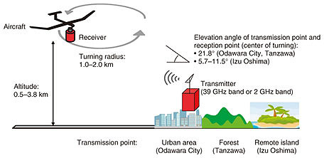
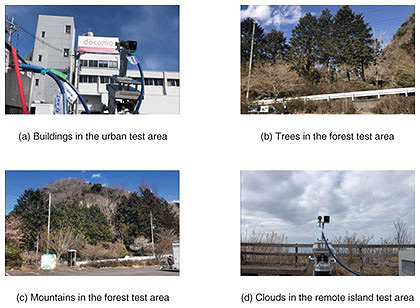
4. Experimental 39 GHz band propagation measurements using a small aircraftTo implement a communication area from an airborne station in 5G evolution & 6G, we conducted an experimental demonstration of radio wave propagation measurements in an urban area (Odawara City, Kanagawa Prefecture), a mountain forest (Tanzawa), and a remote island (Izu Oshima) using a small aircraft (February 15–26, 2021) [10]. Before using the actual HAPS system, we performed an initial experiment to compare the propagation of millimeter wave (39 GHz band) radio signals, which are suitable for 5G high-speed communication, and signals at a lower frequency (2 GHz band), which propagate more easily than millimeter wave signals. These signals were sent from the ground to a receiver mounted on a small aircraft about 3 km above ground level. In the urban environment, we measured the effects of obstacles such as buildings and reflected waves. In the forest, we measured the effects of terrain and trees. And in the remote island, we measured the effects of clouds and low elevation angles above the sea. Our results show that radio wave propagation in the 39 GHz and 2 GHz bands depends on various environmental factors, and changes when the airplane turns. 4.1 Measurement environment and measured itemsFigure 6 shows an illustration of the airborne propagation measurement test. The radio wave transmission points were located in an urban area (Odawara City in Kanagawa Prefecture), a forest (Tanzawa), and a remote island (Izu Oshima), and the reception point was a small aircraft circling with a radius of 1 to 2 km. The elevation angle of the small aircraft (receiving point) from the transmitting point was determined to be equivalent to the use case of a HAPS circling at an altitude of 20 km. Specifically, we assumed a coverage radius of 50 km for an altitude of 20 km in the urban and forest use cases (elevation angle: 21.8°), and a coverage radius of 200 km for an altitude of 20 km in the remote island use case (elevation angle: 5.7–11.5°). In addition to the line-of-sight environment, we also measured the received power with intervening obstacles such as buildings and trees in each use case, as shown in Fig. 7.
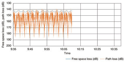
For the transmitting antenna, we selected a product that was able to cover the turning range of the aircraft within the beam width*20, and we fixed the direction of this antenna toward the aircraft’s turning center. The receiving antenna was housed in a mounting frame, and a 3-mm-thick polycarbonate radome*21 designed to cause almost no propagation loss*22 was secured to its base. We also performed an initial experiment in which neither of the transmitting or receiving antennas were provided with tracking functions, and the receiving antenna was fixed directly to the underside of the aircraft. 4.2 Evaluation4.2.1 OverviewFrom this experiment, we found that the maximum reception sensitivity in the unobstructed line-of-sight environments was almost identical to the value obtained by desktop calculations, while the loss of received power in the 39 GHz band was relatively large when there were intervening buildings and trees. To reduce the influence of obstacles of this sort, it will be necessary to consider adopting measures such as site diversity. We also confirmed that the influence of clouds was relatively small in the absence of rainfall. Furthermore, since signals were transmitted and received in this experiment by means of antennas with the same directivity pattern regardless of the aircraft’s position and flight attitude, it also became clear that the received power varies greatly with changes in the angle of the antenna caused by turning of the aircraft. For the practical use of HAPS in the future, these results confirm the importance of using control technology to suppress the effects of turning the aircraft and maintain a constant received power. 4.2.2 Experimental results in OdawaraAs a concrete example of the measurement results, this section describes an experiment that models an urban use case. For the line-of-sight environment in Odawara City, Kanagawa Prefecture with the aircraft circling with a turning diameter of 2 km, Figure 8 shows the time series data of losses in the 39 GHz band. When the maximum receiver sensitivity in the 39 GHz band is calculated from the free space loss shown in Fig. 8, the results generally match the figures obtained in desktop calculations with an error of only about 1.2 dB. On the other hand, the time-series data fluctuated greatly when the aircraft turned, with the average received power decreasing by about 17 dB from the maximum value and the median decreasing by about 14 dB. It is thought that these reductions were mainly caused by fluctuations in the directive gain of the transmitting and receiving antennas, polarization losses*23, and the obstruction of radio waves by the aircraft itself when the underside of the aircraft was facing away from the transmission point.
In the building-occluded environment, the 39 GHz propagation loss has a mean value about 17 dB larger and a median value about 19 dB larger compared with the line-of-sight environment. Although obstruction by buildings also affects the 2 GHz band, the losses are relatively small—about 8 dB in the average value and about 9 dB in the median value—compared with the line-of-sight environment. Furthermore, when the underside of the aircraft is tilted towards the transmitting point, the received power is at least 40 dB greater than when the aircraft is tilted in the other direction.
5. ConclusionIn this article, as part of our efforts toward implementing extreme coverage extension, which is one of the important issues for 5G evolution & 6G, we have described NTN technology, especially HAPS use cases and network configuration/control technology, and we have shown the results of airborne radio propagation tests performed using a small aircraft assuming HAPS use cases. NTT DOCOMO will continue developing NTN technology aimed at achieving extreme coverage extension and technology for realizing HAPS networks, and promoting demonstration experiments and standardization activities. Finally, part of this research and development is carried out by the Ministry of Internal Affairs and Communications (Research and Development for Expansion of Radio Resources; JPJ000254). This article is the reproduction of the special article published in NTT DOCOMO Technical Journal (Vol. 23, No. 2, Oct. 2021). References
Trademark notesAll company names or names of products, software, and services appearing in this article are trademarks or registered trademarks of their respective owners. |
||||||||||||||||||||||||||||||||||||||||||||||||||||||||||||||||||||