|
|||||||||
|
|
|||||||||
       |
Practical Field Information about Telecommunication Technologies Vol. 21, No. 10, pp. 34–38, Oct. 2023. https://doi.org/10.53829/ntr202310pf1 A Case Study of Malfunction of Wireless Communication System Caused by Electromagnetic Disturbance at a Construction SiteAbstractIn this article, we explain a case study of a malfunction of a wireless communication system caused by electromagnetic disturbance at a construction site and countermeasures to prevent such a malfunction. This is the seventy-eighth article in a series on telecommunication technologies. Keywords: electromagnetic disturbance, inverter, isolation transformer, conducted disturbance
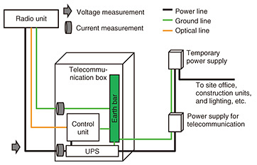
1. IntroductionVarious construction units require high-capacity and low latency wireless communication for remote video monitoring and remote control. An alternating-current (AC) motor is widely used to control AC frequencies by using an inverter. Inside the inverter, the AC power source is converted to a direct-current (DC) power source, then a high-speed switching operation is carried out to convert the DC power source to an AC power source with the desired frequency. This switching operation becomes a cause of electromagnetic disturbance and may affect the operation of surrounding telecommunication units. In this article, a case study of a malfunction of a wireless communication system caused by electromagnetic disturbance generated by a motor, the cause of the malfunction, and countermeasures are described. 2. A case study of malfunction of telecommunication unit in high-capacity wireless communication systemAt a construction site, a customer reported that a wireless communication system has been rebooting on weekdays. Therefore, Technical Assistance and Support Center (TASC), NTT EAST was asked for technical assistance. 2.1 Equipment configuration and malfunction statusThe configuration of the wireless communication system is shown in Fig. 1. The wireless communication system has control and radio units. The control unit is located in a telecommunication box, and the radio unit is located outdoors. The radio unit has optical, power, and ground lines. Each line is connected to the control unit, uninterruptible power supply (UPS), and earth bar. The UPS is powered by a temporary power supply through the power supply for telecommunication. A temporary power supply also supplies power to the site office, various construction units, and outdoor lighting.
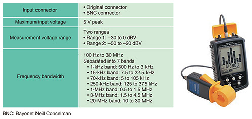
Regarding the status of the malfunction, the radio unit repeatedly rebooted at certain hours of the day during which a conveyor belt operated for transporting sand at the construction site. 2.2 Results of field surveyThere are two types of electromagnetic disturbance that affect telecommunication equipment. One is radiation disturbance that propagates through the air. The other is conducted disturbance that propagates through wired cables. In this construction site case, we focused on measuring conducted disturbance because it seems to have an effect by the belt conveyor. To investigate the effect of conducted disturbance, we measured the common mode voltage and current of a conducted disturbance on the power line and ground line, as shown in Fig. 1. To detect the malfunction, we first measured the common mode voltage using Noise Search Tester [1] developed by TASC. This tester can be easily installed on site with a contactless voltage probe (Fig. 2). The screen graphically displays common-mode-voltage levels in the 1-kHz, 15-kHz, 70-kHz, 250-kHz, 1-MHz, 3-MHz, and 20-MHz frequency bands.
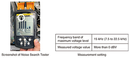
The screenshot of Noise Search Tester measuring common mode voltage is shown in Fig. 3. We confirmed that the highest common-mode-voltage level exceeded 0 dBV in the 15-kHz band, as shown in the white circle in Fig. 3.
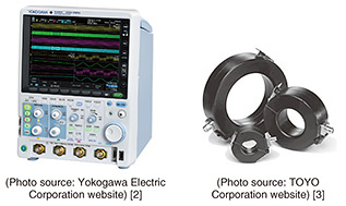
Next, we used an oscilloscope and current and voltage probes to measure the disturbance in detail (Fig. 4). To clarify the relationship between the conducted disturbance and operation of the radio unit, we measured the common mode voltage and current during radio anomalies (when a reboot occurs) and normal conditions, i.e., when the conveyor belt is operating and when it stops.
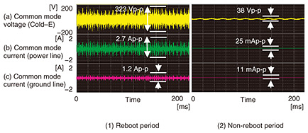
The measurement results are shown in Fig. 5. During the reboot period, it was found that the common mode voltage, which is the voltage between the cold and earth of the power line (Cold–E), was 323 Vp-p and common mode current on the power line was 2.7 Ap-p (Fig. 5(1)). The common mode current on the ground line was 1.2 Ap-p. At the same location, during the non-reboot period, the values were 38 Vp-p, 25 mAp-p, and 11 mAp-p, respectively (Fig. 5(2)). These results indicate that a large common mode voltage and current were generated during a reboot. Comparing the common mode current in the power line (Fig. 5(b)) and in the ground line (Fig. 5(c)), we confirmed that the common mode current on the power line is larger than that on the ground line.
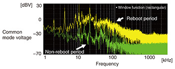
To clarify the frequency of the disturbance, we analyzed the common mode voltage during the reboot and non-reboot periods using the fast Fourier transform (FFT) method. As shown in Fig. 6, the analysis results indicate that the disturbance had a wide frequency range of 2 kHz to 1 MHz.
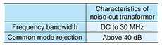
2.3 Estimation of malfunction causeThe above results indicate that (i) the radio unit reboots when the conveyor belt is operated and (ii) high-level common mode voltage and current appear on the power and ground lines during the operation of the conveyor belt. Therefore, we estimated that the conducted disturbance generated from the motor of the conveyor belt caused the reboot of the radio unit. 2.4 Countermeasures and ResultsCountermeasures against the effects of conducted disturbance on the wireless communication system include the following: (1) Isolate or maintain disturbance sources: We must isolate or remove the disturbance sources from the same power supply of the radio unit. If the disturbance sources could not be isolated or removed, we must maintain the disturbance sources. (2) Filter conducted disturbance: If we could not remove the disturbance sources, we should consider installing a noise filter, isolation transformer, etc. on the telecommunication, power, and ground lines of the paths of the conducted disturbance for filtering it. (3) Replace telecommunication units: Replace disturbance-affected units that are more resistant to disturbance. In this case study, it was difficult to apply disturbance countermeasures for the conveyor belt. Since the radio unit is specified in this construction site, we cannot replace it. Therefore, we decided to install a noise-cut transformer (the characteristics of which are shown in Table 1) in the power line connecting to the radio unit, which is the path of the disturbance.
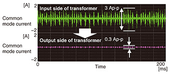
The measured common mode current after installation of the noise-cut transformer is shown in Fig. 7. This result indicates that the common mode current in the power line (measured at the input and output sides of the transformer) during operation of the conveyor belt decreased from 3 to 0.3 Ap-p. As a result of the noise-cut transformer action, the radio unit no longer had rebooting issues.
3. ConclusionA case study of a malfunction of the radio unit of a wireless communication system caused by electromagnetic disturbance at a construction site and countermeasures to prevent the malfunction were described. Though inverters are used to maintain efficiency of the power system at construction sites and in photovoltaic power systems, they can be a source of electromagnetic disturbance that affects telecommunication systems. It is important to investigate the inverters before installation and take necessary countermeasures against such disturbance. At TASC, we will continue to play a role in reducing maintenance operation in the field by providing the knowledge we have accumulated. To reduce malfunctions caused by electromagnetic disturbance, radio, induction, and lightning and improve the reliability of telecommunication services, the EMC Engineering Group of TASC will continue to engage in technical cooperation, development, and dissemination of technology through technical seminars and other activities. References
|
||||||||