 |
|||||
|
|
|||||
|
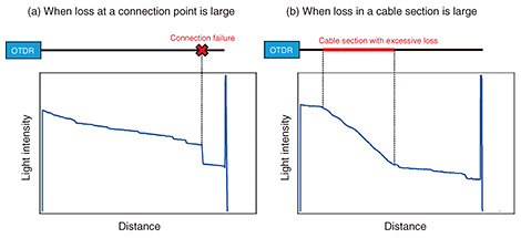
Practical Field Information about Telecommunication Technologies Vol. 23, No. 5, pp. 56–60, May 2025. https://doi.org/10.53829/ntr202505pf1 OTDR Waveform Evaluation Tool Enabling Automatic Identification of Location and Cause of FaultsAbstractAn optical time-domain reflectometer (OTDR) is commonly used to check the condition of optical fiber cables. However, identifying the location and cause of faults in optical fiber cables using an OTDR requires advanced skills and a substantial workload to analyze the obtained waveform. Technical Assistance and Support Center, NTT EAST developed an OTDR waveform evaluation tool to automatically identify abnormal sections in optical fiber cables from waveforms obtained with an OTDR. This article presents an overview of this tool. Keywords: OTDR, waveform analysis, abnormality determination 1. IntroductionOutdoor telecommunication facilities are exposed to harsh natural environments and subject to unexpected faults. To restore these facilities quickly, it is crucial to swiftly and accurately identify the location and cause of the fault. An optical time-domain reflectometer (OTDR) is commonly used to check the condition of optical fiber cables [1]. However, identifying the location and cause of faults in optical fiber cables using an OTDR requires advanced skills and a substantial workload to analyze the obtained waveform. To address this issue, Technical Assistance and Support Center (TASC), NTT EAST developed an OTDR waveform evaluation tool that automatically identifies abnormal sections in optical fiber cables from the obtained waveforms. 2. Problems with OTDR waveform evaluationAn OTDR injects a test light into an optical fiber and measures the intensity of the backscattered and reflected light along the length of the optical fiber cable. Examples of waveforms obtained with an OTDR are shown in Fig. 1. If the loss at a connection point is large, the light intensity will decrease locally at the connection failure location, and a step-like waveform will be observed (Fig. 1(a)). Conversely, if the loss in a cable section is large, the light intensity decreases continuously over a certain distance, and the slope of the section with respect to distance increases, as shown in Fig. 1(b). Therefore, by analyzing the waveform with an OTDR, the location and cause of faults in optical fiber cables can be estimated.
Although an OTDR is an effective tool for identifying the location and cause of faults, advanced skills and a substantial workload are required to analyze waveforms obtained with an OTDR. The conventional process for analyzing OTDR waveforms is shown in Fig. 2. This process involves the following steps. First, the waveform is visually inspected to identify suspected fault locations along the optical fiber cable. Next, analysis markers are placed at each suspected fault location. Finally, the losses (or reflection) at these locations are analyzed. Since there is usually no single fault location, advanced skills are required to analyze waveforms and identify even the slightest abnormalities. The volume of OTDR measurement data is proportional to the number of fibers and wavelengths of the test light. Thus, the analysis steps mentioned above must be repeated for all OTDR measurement data, leading to an enormous workload. To address these problems, TASC developed a tool that automatically identifies abnormal sections in optical fiber cables from OTDR waveforms.
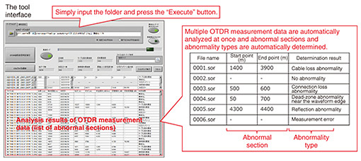
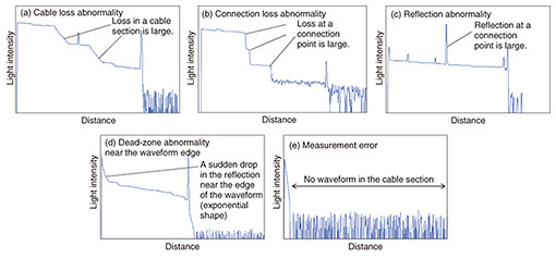
3. OTDR waveform evaluation tool3.1 Overview of toolAn overview of the developed OTDR waveform evaluation tool is shown in Fig. 3. The tool is data analysis software that runs on a Windows personal computer and allows for easy identification of abnormal sections and abnormality types in OTDR waveforms. By inputting the OTDR measurement data (the Standard OTDR Record (SOR) data format extension file [2]), the tool automatically performs a batch waveform analysis on all the measurement data in the folder, identifies abnormal sections and abnormality types, and displays the results in a list format. The abnormality type that can be detected with this tool and examples of their OTDR waveforms are shown in Fig. 4. The tool can automatically determine five types of abnormality: cable loss abnormality (Fig. 4(a)), connection loss abnormality (Fig. 4(b)), reflection abnormality (Fig. 4(c)), dead-zone abnormality near the waveform edge (Fig. 4(d)), and measurement error (Fig. 4(e)). Even if multiple abnormalities are present on a single waveform, the tool can identify the abnormality type for each individual abnormal section, allowing for comprehensive identification of all abnormalities in the waveform. We describe the process of abnormality determination with this tool and its other functions.
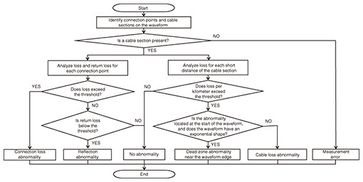
3.2 Process of determining abnormality typeThe flowchart of the abnormality determination process using the tool is shown in Fig. 5. The tool incorporates an algorithm that automatically identifies connection points and cable sections in the OTDR waveform and analyzes them separately. For connection points, the loss and return loss are analyzed. Connection points where the loss exceeds the threshold are determined to have a connection loss abnormality, and connection points where the return loss is below the threshold are determined to have a reflection abnormality. For cable sections, the loss in each short section is analyzed. Sections where the loss (converted to loss per kilometer) exceeds the threshold are determined to have a cable loss abnormality. If the section is located at the start of the waveform and the waveform has an exponential shape, it is judged to be a drop in reflection caused by a connection failure between the cable and OTDR and determined to be a dead-zone abnormality near the waveform edge. If a cable section is not recognized, it is determined to be a measurement error. This abnormality determination process is designed to be carried out sequentially on all OTDR measurement data, enabling the tool to automatically determine abnormality type in a large number of OTDR waveforms.
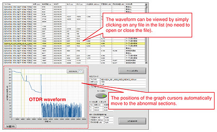
3.3 Other functions of the toolIn addition to the automatic analysis of waveforms, the OTDR waveform evaluation tool also supports manual analysis. An image of the operation interface for manual analysis is shown in Fig. 6. When any file in the list is clicked, the OTDR waveform of the selected data is displayed in the graph box and can be manually analyzed using the vertical and horizontal graph cursors. Waveforms can be viewed instantly without opening and closing files, and the position of the graph cursors automatically moves to the abnormal section. Therefore, manual analysis is made more efficient than before. The list of abnormality determination results can be searched by filtering according to conditions such as file name or abnormality type, and the results can be exported in CSV (comma-separated values) format. As described above, the tool supports many additional functions, enabling it to be used flexibly in a variety of scenarios.
4. ConclusionAn overview of the OTDR waveform evaluation tool was provided. This tool enables the analysis of OTDR waveforms without requiring advanced skills and making the analysis process more efficient. We expect that using this tool will accelerate the identification of the location and cause of faults in optical fiber cables deployed in telecommunication networks. TASC will continue contributing to solving on-site problems through technical support for those involved in the maintenance and operation of telecommunication facilities. References
|
|||||


