|
|||||||||||||||||
|
|
|||||||||||||||||
|
Feature Articles: High-value-added Transmission Technologies through the Convergence of Optical and Wireless Technologies for IOWN/6G Vol. 24, No. 2, pp. 38–44, Feb. 2026. https://doi.org/10.53829/ntr202602fa4 Research and Development of Optical-wireless Integrated Transmission Technology for Providing Ultra-high-speed/capacity Communications in IOWN/6GAbstractNTT’s current research and development aims to implement innovative network and information-processing technologies by integrating sixth-generation mobile communications system (6G) networks with the Innovative Optical and Wireless Network (IOWN). This article introduces a photonics-assisted matrix radio beamformer, which is an initiative of NTT Network Innovation Laboratories for implementing IOWN/6G and will enable ultra-high-speed/capacity communications. Keywords: 6G, array antenna, photonics-assisted matrix radio beamformer  1. IOWN: A concept supporting the evolution of mobile communication systemsThe evolution of mobile communications technology and services is rapid, i.e., new generations appear approximately every ten years. NTT DOCOMO has been offering commercial fifth-generation mobile communications system (5G) services since 2020. One of the features of 5G is that it uses a high-frequency band called millimeter waves. Therefore, 5G enables ultra-high-speed wireless communication of several gigabits per second across a dramatically wider frequency bandwidth. Some countries are beginning to consider commercializing the next generation of mobile communications, 6G, around 2030. The International Telecommunication Union - Radiocommunication Sector (ITU-R) has designated 6G as IMT-2030 (International Mobile Communications-2030) and plans to define technical performance requirements and evaluation methods between 2024 and 2026 and move toward standardization between 2027 and 2030. ITU-R has also decided that discussions on mobile use of the sub-terahertz band*1, which covers frequencies even higher than that of millimeter waves, will be held after World Radiocommunication Conference 2031 [1]. We aim to continue evolving mobile communications systems by integrating the elemental technologies of the Innovative Optical and Wireless Network (IOWN)—an innovative network and information-processing infrastructure proposed by NTT characterized by ultra-large capacity, ultra-low latency, and ultra-low power consumption—with 6G. This integration (IOWN/6G) seeks to satisfy the diverse requirements of 6G, namely, extremely high data rate/capacity, extreme coverage extension, extremely low energy consumption & cost, extremely low latency, extremely high reliability, and extremely massive connectivity & sensing [2]. This article introduces one of the research and development (R&D) initiatives for implementing IOWN/6G, a photonics-assisted matrix radio beamformer, which uses optical circuits to enable ultra-high-speed/capacity communication.
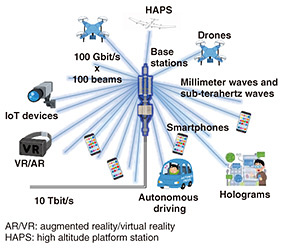
2. Expectations for ultra-multibeam communicationsDue to the widespread use of smartphones and Internet of Things (IoT) devices, mobile traffic is increasing exponentially yearly, which is driving a continuing demand for increased communication capacity of mobile communication systems to accommodate that increasing traffic. Methods being considered to increase communication capacity include (i) increasing the amount of information per symbol (increasing the number of modulation levels), (ii) increasing the degree of spatial multiplexing*2 by applying parallel communication using multiple antennas, and (iii) using high-frequency bands that allow for wideband use. To foster wireless resources for 6G, the use of high-frequency bands above 100 GHz, known as the sub-terahertz band, is being considered, and research and discussions on using the sub-terahertz band are becoming more active worldwide. To compensate for the propagation loss of radio waves using such high-frequency bands, base stations must be configured as an array antenna*3. Using beamforming technology, which controls the phase of the signal input to each antenna element and gives radio waves directionality according to the direction of the communication partner, makes it possible to transmit radio waves with a narrow beam to the partner device with pinpoint accuracy. Therefore, radio interference with other devices can be suppressed. When beamforming technology is combined with multiple input and multiple output (MIMO) communication, which is a method of increasing the above-mentioned spatial-multiplexing level (when multiple beams are transmitted simultaneously), complex signal processing to suppress interference becomes unnecessary, and both power savings and high-capacity communication become possible. At NTT Network Innovation Laboratories, we are developing a technology called a photonics-assisted matrix radio beamformer to achieve ultra-multibeam-based, high-capacity wireless transmission of 100 Gbit/s/beam × 100 beams/base station (or 10 Tbit/s/base station) (see Fig. 1).
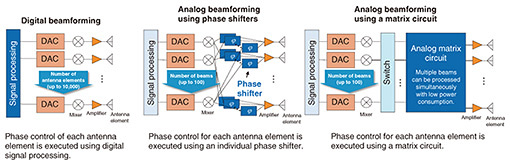
3. Application of optical technology to wireless communicationConventional beamforming methods are shown in Fig. 2. 5G uses beamforming implemented with electrical circuits, but it is thought to be difficult to apply to multiple element array antennas, which are expected to be required for communications using the sub-terahertz band, ranging from several thousand to 10,000 elements. For example, to implement digital beamforming, digital-to-analog converters (DACs) and mixers are required for each antenna element. The amount of signal processing will also increase with the number of antenna elements and beams, so power consumption is expected to increase significantly. Analog beamforming using phase shifters requires a phase shifter for each antenna element, so the number of phase shifters equals the number of beams to be multiplexed, and individual control of the phase shifters are necessary, which are expected to be difficult to integrate with the narrow spacing between antenna elements using the high-frequency band.
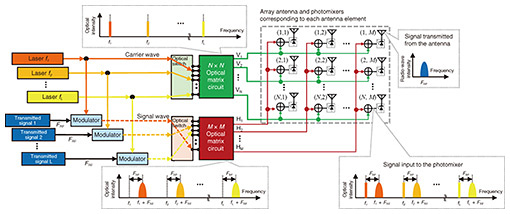
On the contrary, analog beamforming using matrix circuits is, in principle, suitable for generating multiple beams. It is promising because it can simultaneously control multiple beams in a specified direction (according to the input port) by using passive circuits that do not require a power source. However, implementing matrix-circuits-based analog beamforming with high-frequency electrical circuits requires a three-dimensional configuration using metal waveguides, and meeting that requirement poses challenges from the standpoint of processing. With those challenges in mind, NTT Network Innovation Laboratories is considering implementing analog beamforming by using compact, low-loss (power-saving) optical circuits as matrix circuits. Optical semiconductor technology, including silicon photonics, has made remarkable progress, which has led to the introduction of optical devices with higher performance, smaller size, and lower cost. These features have led to the application expansion of optical semiconductors beyond conventional optical communication technology to include wireless communication. A semiconductor device called a photomixer outputs a beat signal (i.e., an electrical signal corresponding to the difference frequency) when optical waves (lasers) with different frequencies are input into it. Since the frequency of the output radio waves can be controlled precisely and flexibly by simply changing the laser frequency of the photomixer, this devise is being widely researched as a method for generating radio waves in high-frequency bands including the sub-terahertz band [3]. By using planar lightwave circuit (PLC) technology, developed for optical communications, to implement large three-dimensional matrix circuits for analog beamforming, which has been a difficult task with conventional electrical circuits, it is possible to achieve comprehensive miniaturization and planarization of matrix circuits compatible with array antennas with several thousand to 10,000 elements at low cost. By applying wavelength-division multiplexing (WDM), a technology used in optical communications, it is easy to increase the number of simultaneous beams generated, thus significantly increasing base-station capacity compared with that possible with conventional systems. 4. Photonics-assisted matrix radio beamformerNTT Network Innovation Laboratories is researching a photonics-assisted matrix radio beamformer, which enables analog beamforming through optical matrix circuits and WDM optical communication technology [4]. Using this beamformer enables the construction of extremely compact circuits for interference-free ultra-multibeam communication via large-scale array antennas using high-frequency bands. The principle of a photonics-assisted matrix radio beamformer compatible with an array antenna with N × M elements is explained below (Fig. 3).
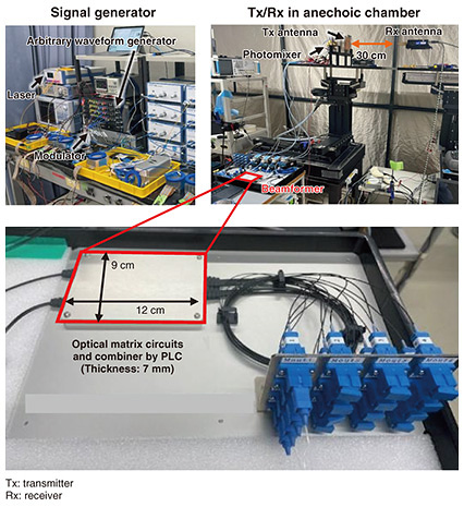
The optical carrier wave from a laser source with frequency f1 is split in two, and one is single-sideband modulated with the radio signal (frequency fRF) to be transmitted. When these two optical waves, carrier wave and sideband wave (signal wave), are input into a photomixer, a radio signal with frequency fRF representing the difference between the frequencies of the two waves is output as a beat signal. However, the phase of the output radio signal reflects the phase difference between the two input waves. Taking advantage of this property, the photonics-assisted matrix radio beamformer executes two-dimensional beamforming by controlling the phase of the radio signal fed to each antenna element of an array antenna at the optical stage before the signal enters the photomixer. The beam direction from the antenna is decomposed into elevation and azimuth components. A matrix circuit weights the phases in both directions for each carrier and signal wave, assigning a phase to each powered antenna element so that the radio waves are reinforced in a specific direction. Thus, two-dimensional phase weighting is applied to the radio signal. By using an optical switch to select the input port of the optical matrix circuit according to the elevation angle to which the beam is directed, the same carrier waves are output from all output ports (V1, V2, ..., VN) of the N × N optical matrix circuit, but each output is subjected to the desired phase weighting. Similarly, if an optical switch is used to select the input port of the optical matrix circuit according to the azimuth angle to which the beam is directed, the same signal waves are output from all output ports (H1, H2, ..., HM) of the M × M optical matrix circuit, but each output is subjected to the desired phase weighting. These carrier and signal waves are combined in combinations corresponding to the N × M array of antenna elements (N, M) and input into the photomixers arranged in a matrix, and radio signals that reflect the phase weighting in the two-dimensional directions of elevation and azimuth angles are transmitted from each antenna element. The radio waves transmitted from each antenna element are phase-weighted to reinforce each other in a specific direction, forming a narrow beam. Since the optical matrix circuit supports multiple inputs, it is possible to control and generate multiple beam signals (with number of beams L) simultaneously by using the same circuit by WDM with a laser for multiple frequencies (ƒ1, ƒ2, • • • , ƒL). 5. Experimental trial on two-dimensional multiple-beam transmission using optical circuits in 150-GHz bandTo demonstrate the principle of the photonics-assisted matrix radio beamformer, we prototyped a 16-element beamformer and experimentally tested it in an anechoic chamber (Fig. 4). Compatible with a 4 × 4 element array antenna, the beamformer is constructed as a palm-sized PLC. The section from the two 4 × 4 optical matrix circuits to the circuit that combines the signals input to the photomixer is constructed with optical circuits. An output (via optical fiber) can be connected to the photomixer. Each of the two matrix circuits has four input ports, which can be switched to enable two-dimensional beamforming in 16 directions.
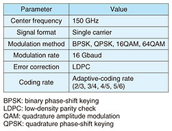
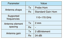
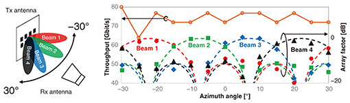
In the signal generator, a laser source is used to generate two optical waves with difference in frequency of 150 GHz, and one of the waves is modulated using an in-phase and quadrature modulator and arbitrary waveform generator. The optical signal phase-weighted by the beamformer is input to the photomixer coordinated with each antenna element and converted into a 150-GHz band radio signal. In the anechoic chamber, a wideband signal (experimental specifications of which are listed in Table 1) was transmitted in each direction from a 2 × 4 element array antenna (specifications of which are listed in Table 2) and received with a horn antenna 30 cm away. To confirm the performance of the beamformer, the received power and throughput of each beam were measured at intervals of 5° from the transmitting antenna. The measurement results for a plane with an elevation angle of −7° from the transmitting antenna are plotted in Fig. 5. The four-color plot, in which the received power of each beam is normalized by its maximum value, and the dashed line showing the array factor (directivity of the transmitted radio wave calculated under the assumption of an ideal beamformer and antenna) corresponds to the right-side vertical axis. As these values increase, the signal-to-interference-and-noise ratio (SINR)*4 becomes higher, and throughput also becomes higher. The solid orange line represents the maximum throughput measured at each azimuth angle and corresponds to the left-side vertical axis. By appropriately switching the selected beam, 64QAM (quadrature amplitude modulation), a high-order modulation method, was selected in all directions, and transmission of over 64.0 Gbit/s was confirmed. We also measured the throughput when multiple beams were transmitted simultaneously. Due to constraints of the experimental equipment, the inner 2 × 2 elements of the 2 × 4 element array antenna were used as the transmitting antenna, and the positions of the two receivers (azimuth, elevation) were respectively (−6°, 19°) and (19°, 19°). Degradation in the SINR due to interference between the two beams was only 0.5 dB, and the maximum transmission throughput for the two beams combined was 136 Gbit/s. The above experimental results validate the principle of the photonics-assisted matrix radio beamformer.
6. Future workWe achieved the first demonstration of 100 Gbit/s-class multiple-beam wireless transmission in the sub-terahertz band by using optical circuits. Through this experiment, we validated the principle of a photonics-assisted matrix radio beamformer. We will continue to advance the adoption of multiple elements, multiple beams, and multiple band technologies while aiming to establish wireless communication technology that will support a beamformer capable of generating 100 Gbit/s × 100 beams in the sub-terahertz band. We will also continue to promote R&D in the fields of radio-wave imaging and sensing. References
|
|||||||||||||||||