|
|||||||||||||||||||||
|
|
|||||||||||||||||||||
|
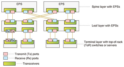
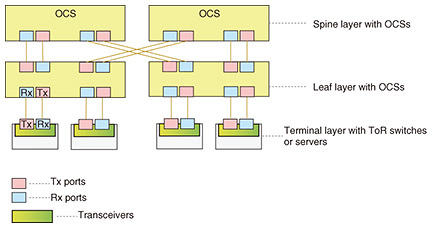
Regular Articles Vol. 24, No. 6, pp. 60–71, June 2026. https://doi.org/10.53829/ntr202606ra1 Reliable Operation Technologies for Datacenter Networks Composed of Optical Circuit SwitchesAbstractOptical circuit switches (OCSs) are attracting considerable attention as a key enabler for next-generation datacenter networks (DCNs), as they allow networks to improve capacity, latency, and energy efficiency by eliminating optical–electrical–optical conversions. However, the adoption of OCS-based architectures fundamentally changes network operations, particularly with respect to the verification of fiber connectivity and link quality prior to service deployment. Unlike conventional electrical packet-switched networks, OCS-based networks do not inherently support packet-based probing, topology discovery, or continuous link monitoring. The fiber-layer connectivity and quality of optical fibers, both between OCSs and between OCSs and terminal nodes, must therefore be verified through optical signal probing and power measurements. Keywords: optical circuit switch, datacenter network, fiber inspection, topology verification  1. IntroductionThe rapid expansion of artificial intelligence (AI) and high-performance computing workloads has dramatically increased traffic inside datacenter networks (DCNs). Conventional DCNs based on electrical packet switches (EPSs) offer flexible packet-switching capabilities; however, as network scale and bandwidth increase, they exhibit inherent limitations, including packet processing delays, buffering overhead, and elevated power consumption (Fig. 1). These limitations have motivated the introduction of optical communication technologies into DCNs (Fig. 2), especially in environments where both transmission capacity and energy efficiency are critical [1].
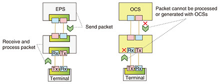
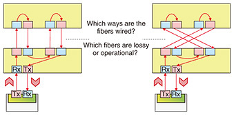
Optical circuit switches (OCSs) are particularly attractive because they establish direct optical paths without repeated optical–electrical conversion. In principle, this allows bandwidth-rich, low-latency communication and reduces the power consumption associated with packet processing. As recent production systems and research prototypes have shown, OCSs can be incorporated into DCNs to support both capacity scaling and improved energy efficiency [1–3]. The deployment of OCSs also changes the operational assumptions that have long been taken for EPS-based networks (Fig. 3). In a packet-switched network, operators can validate topology and detect fiber-wiring problems through packet exchange between network devices [4, 5]. Specifically, layer-2 or layer-3 protocols such as the Link-Layer Discovery Protocol (LLDP) and other control-plane or management-plane mechanisms make it possible to estimate the actual connectivity of neighboring devices [6, 7]. However, OCSs simply switch optical signals from input ports to output ports. They neither send packets nor receive and process them. As a result, conventional topology discovery and link-monitoring mechanisms cannot be directly applied to OCS-based DCNs.
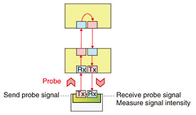
This limitation becomes particularly critical prior to service initiation. Large-scale OCS-based DCNs involve a vast number of optical fibers that are manually installed both between OCSs and between OCSs and terminal nodes, such as transceivers installed in top-of-rack (ToR) switches or servers (hereafter referred to simply as terminals). During deployment or expansion, some fibers may be miswired or physically degraded. Therefore, it is essential to verify that the actual fiber connectivity matches the intended topology and that the loss of each link remains within the allowable transceiver budget. If such verification is omitted or conducted inadequately, unexpected failures may occur after the network begins operation [6, 7]. The challenge is that fiber verification must rely solely on optical signal measurements at endpoint terminals (Fig. 4). Specifically, probe signals are transmitted from these terminals through the target fibers and received at corresponding terminals, and the connectivity and quality of each fiber must be estimated from the observed signal power. Since operators cannot directly observe the physical topology, they must instead interpret measurement results that reflect signal propagation over unknown optical paths. Fiber verification in OCS-based DCNs is thus fundamentally an estimation problem. To address this problem while ensuring both correctness and efficiency, it is essential to model signal propagation, derive operationally meaningful loss thresholds based on the transceiver power budget, and design probing strategies that prevent or resolve the ambiguities illustrated in Fig. 5.
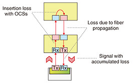
This article presents a unified technical framework of our fiber-verification technologies for OCS-based DCNs. Specifically, it integrates two complementary contributions. The first is an efficient inspection and certification method for fibers between OCS devices in hierarchical OCS DCNs [6]. Since hierarchical OCS-based DCNs are essential for network scalability [8, 9], the establishment of OCS-to-OCS fiber-inspection mechanisms is indispensable. The second is a topology and quality verification method for fibers between terminals and OCSs in the OCS-based DCNs [7]. Although the two problems differ in network structure and in what can be measured directly, they are connected by the same underlying principles: loss-aware verification, ambiguity-resolving probing, and scalability through careful algorithmic design. 2. Verification requirements in OCS-based DCNsBefore describing the two verification technologies individually, we clarify the common requirements that any practical solution must satisfy. First, the solution must determine whether the actual fiber topology matches the intended design. In a datacenter, this includes identifying fibers that are connected to the wrong ports or wrong devices. Second, the solution must determine whether each fiber can support actual communication during service operation. A fiber that merely allows optical signal transmission is not necessarily operationally viable if its loss exceeds the transceiver power budget. Third, the solution must scale to large networks. A method that ensures correct estimation results requires one-by-one manual inspection of tens of thousands of fibers and is therefore impractical. These requirements make fiber verification fundamentally different from a simple continuity test. The objective is not simply to determine whether some signal can be received; it is to determine whether the network can be operated safely and predictably. A common physical basis of both verification problems is the signal propagation model (Fig. 6). If a signal is transmitted with optical power Pt and received with optical power Pr after traversing OCSs and fibers, then the total loss along the path is the sum of switch insertion losses and fiber losses. This relationship can be described as
where LOCS and Lfiber denote the loss of each OCS and fiber, respectively.
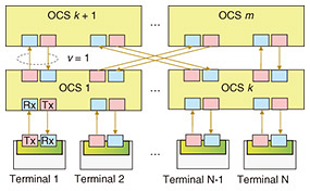
Because no amplification is assumed in the inspection paths considered here, the received power monotonically decreases as loss accumulates. Verification therefore becomes an inverse problem: from a measured end-to-end power level, estimate whether one or more fiber segments are faulty and identify which ones. Another key common concept is the transceiver link budget. Let LB denote the link budget of the terminals or transceivers used in the target DCN. Operational communication is possible only if the total end-to-end loss remains below this budget. This means that verification must not be based on arbitrary thresholds; it must be based on a loss bound that is consistent with the actual equipment used in the network. Therefore, in practice, verification aims to determine whether the installed fibers satisfy the required topology and whether their losses are sufficiently low to ensure reliable communication in the operational network. 3. Efficient fiber inspection between OCSs3.1 Network model and inspection targetWe first consider hierarchical OCS-based DCNs in which leaf OCSs and spine OCSs are connected with a large number of fibers [6]. In such a network, the set of k leaf OCSs and the set of m spine OCSs form a multi-stage fabric (Fig. 7), often based on a Clos or twisted folded-Clos structure [8]. During installation, multiple fibers are manually placed between each leaf–spine pair according to a blueprint. The inspection target is the set of these inter-switch fibers.
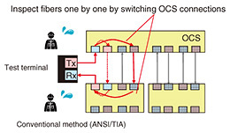
The objective is to identify all malfunctioning fibers before the network begins operation. In practice, this means detecting at least two classes of problems. The first class is miswiring, in which a fiber is connected to the wrong port or wrong switch, thus does not achieve the intended topology. The second class is excessive loss, in which the fiber is physically present along the intended route but cannot be used safely because its loss is too high. Since the operator is interested in whether the network can be operated, not simply whether a signal can be observed, the classification must be tied to the transceiver budget used in the target DCN. 3.2 Why the conventional method is inadequateThe conventional method standardized in the American National Standards Institute/Telecommunications Industry Association (ANSI/TIA) executes Tier-1 certification by attaching a light source and power meter to the two ends of a fiber under test and measuring its loss one by one (Fig. 8). In a large OCS-based DCN, this leads to two major inefficiencies. First, the tester must be repeatedly detached and reattached for different switch pairs, which introduces substantial manual work. Second, every fiber must be probed individually. When the network contains tens of thousands of fibers, the total inspection time can easily reach person-week order [4].
One might attempt to accelerate the process by fixing a tester to one OCS and probing multiple fibers through longer optical paths. However, this immediately creates ambiguity. If the received signal is weaker than expected, it is not obvious which fiber on the path caused the excess loss. Even when a signal is received, that does not necessarily prove that the intended path has been formed. A miswired fiber may participate in an unintended path that still delivers light back to the tester. This means that naive multi-fiber probing can sacrifice correctness for speed, which is unacceptable in a pre-operation verification process. 3.3 Signal propagation and allowable loss for OCS–OCS pathsLet q be a probe path that traverses a set of switches Sq and a set of fibers Eq. If the transmitted probe power is P0, the received probe power Pq is expressed as
Here, Ls denotes the insertion loss of switch s on the specific transmit/receive (Tx/Rx) connection pair used in the path, and L(e) denotes the loss of fiber e. Since the insertion loss of OCSs can vary by port pair, such values are treated explicitly rather than being assumed constant. This is important because practical inspection must be consistent with actual hardware characteristics. For a given target fiber e on path q, the method estimates a conservative upper bound on its loss by working on the assumption that all other fibers on the same path have only the minimum unavoidable loss Lmin. This gives
If the same fiber is inspected through several different paths, the minimum of the resulting upper bounds is taken as the effective estimate of its maximum possible loss. This conservative formulation is important because it ensures that if a fiber is certified as usable, it truly satisfies the operational condition. In a two-level hierarchical OCS DCN, an operational signal may traverse at most three OCSs and two fibers. Therefore, if the transceiver budget is Pb and maximum OCS insertion loss in the network is
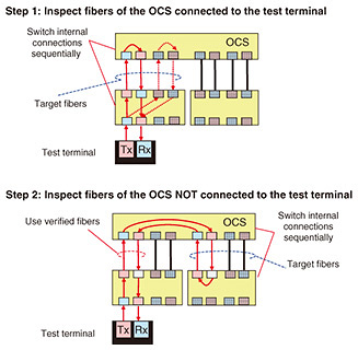
A fiber, the estimated maximum loss of which exceeds Lok, cannot be safely used for operation. The signal threshold used for path evaluation is then derived from this allowable loss. A strong enough received signal indicates that no fiber on the path violates the loss requirement, whereas a weaker signal indicates that at least one fiber on the path may be problematic. 3.4 Path ambiguity and the uniqueness conditionThe major conceptual contribution of the OCS–OCS method is not only the loss estimation but the way ambiguity is avoided. The method does not permit arbitrary long probe paths. Instead, it constructs paths so that the result of receiving a signal can be interpreted unambiguously. The central sufficient condition is that the planned test path contains no more than one unverified fiber in each of the up and down directions. All ports not belonging to the path are configured in the internally unconnected state. Under the assumptions that Tx ports are connected only to Rx ports and that same-layer switches are not connected directly, this condition guarantees that only the intended blueprint path can carry the signal. In other words, the measurement becomes topologically interpretable. This condition resolves the wiring ambiguity that otherwise arises in hierarchical OCS networks. A received signal is no longer merely evidence that some path exists; it becomes evidence that the specific planned path exists. This is what enables the method to verify multiple fibers without sacrificing correctness. 3.5 Inspection procedureThe inspection begins by attaching a tester to one leaf switch, which is practical because leaf switches typically have idle or externally reserved ports. The first round verifies fibers directly connected to that tester-attached switch. Once a subset of fibers has been verified as correctly wired and healthy, those fibers are treated as trusted segments. In later rounds, the method uses those verified segments to construct longer inspection paths that reach additional unverified fibers while still satisfying the path-uniqueness condition (Fig. 9).
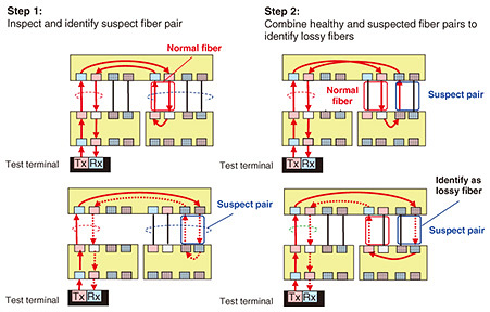
For each path, the received signal level is classified into categories. If the received power exceeds the healthy threshold, the fibers on the path are consistent with the allowable loss requirement. If the signal is present but weak, one or more fibers on the path may be lossy and become suspects for additional inspection. If no signal is received, the path contains either severe loss or miswiring. Because the method is conservative, it is designed to avoid false negatives; a fiber that is certified as healthy is one that can truly be used in the operational DCN. In particular, when the received power Prx is below the threshold By attaching a single test terminal to a specific OCS and dynamically reconfiguring internal connections of the OCSs to change inspection paths, our inspection method enables automatic verification of both fiber connectivity and quality without manual intervention (Fig. 10).
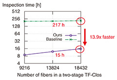
3.6 EvaluationsTo evaluate the effectiveness of our fiber-inspection method, we compared its inspection time with that of the conventional method under a large-scale DCN setting (Fig. 11).
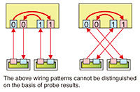
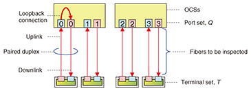
In this evaluation, we consider a two-stage twisted and folded (TF)-Clos network where the total numbers of fibers to be inspected were 9216, 13,824, and 18,432, which are consistent with the scale of hyperscale DCNs. The time required for a single inspection operation was assumed 5.0 seconds, corresponding to the switching time of a typical micro-electro-mechanical-system (MEMS)-based OCS [10]. Under these conditions, the total inspection time of the conventional method, which inspects fibers individually for each OCS pair, was estimated to be approximately 217 hours (about one week). In contrast, our method fully automates the inspection process and significantly reduces the number of required inspection operations by reusing verified fibers and probing multiple fibers through carefully designed paths. As a result, the total inspection time of our method was reduced to approximately 15 hours, which can be completed within a single day. This corresponds to an improvement of approximately 13.9 times compared with the conventional method. These results indicate that our method enables practical and scalable fiber inspection for large-scale OCS-based DCNs, where conventional manual or sequential inspection methods are no longer applied. 4. Topology and quality verification of fibers between terminals and OCSsWe next consider the verification of fibers between terminals and OCSs in OCS-based DCNs. In this case, each terminal is connected to an OCS port through a duplex fiber. Because commercial transceivers often provide digital diagnostic monitoring (DDM) functions, the transmitted and received powers at the terminals can be measured directly. This is an advantage because it eliminates the need for a dedicated external tester at every step. However, it also enables parallel probing from many terminals, and that is precisely what creates a new ambiguity problem. 4.1 Challenge: indistinguishable topologyThe most important difficulty in terminal–OCS fiber verification is not merely that some measurements are noisy or that some fibers may be faulty. The core difficulty is that different physical fiber wirings can produce the same observation under a given OCS configuration. In other words, the relationship between physical topology and observed received signals is not one-to-one (Fig. 12).
To understand this, suppose that several terminals transmit probe signals simultaneously while the OCS establishes multiple internal connections. The terminals only observe which signals are received and at what power levels. They do not observe the precise internal route taken by each optical signal. Because the OCS simply forwards light from an Rx port to a configured Tx port, and because several internal connections may coexist, there may be multiple physical fiber topologies that are all consistent with the same external observation. This means that a naive measurement, even if all expected terminals receive signals, does not necessarily prove that the installed topology matches the intended one. A miswired topology may accidentally produce the same received-signal pattern as the correct topology under one probing configuration. If the operator accepts that state as valid, later service configurations may create paths between unintended terminals or may cause unexpected budget exceedance because the actual signal path differs from what was assumed. This is why topology verification in terminal–OCS networks cannot be reduced to a simple continuity or packet-reachability check [5]. The indistinguishable-topology issue is therefore an observability problem. The system being measured is underdetermined unless the probing patterns are designed in such a way that each possible topology leaves a distinguishable signature in the set of observations. This is the central reason a dedicated verification algorithm is required. 4.2 Why conventional checks are insufficientThe conventional verification methods are inadequate for two reasons. First, packet-based techniques, such as LLDP, cannot be applied directly because OCSs do not generate or process packets. Second, even if one tries to use simple signal presence or packet transfer between terminals, this still does not guarantee that the topology is correct under all intended OCS configurations. A topology that works under one configuration may fail under another if the actual path includes different insertion losses than expected. Thus, terminal–OCS verification must solve two coupled subproblems. It must identify the actual topology and must determine whether the connected fibers satisfy the allowable loss requirement derived from the transceiver budget. Solving only one of these is not sufficient for reliable operation. 4.3 Network model and signal modelThe OCS network is modeled as a set of terminals T and set of OCS duplex ports Q (Fig. 13). Each terminal is connected to exactly one OCS port through a duplex fiber, and each duplex port is connected to at most one terminal. The OCS can create internal connections between any Rx and Tx ports, including loopback connections that return an incoming signal back through the same duplex port.
For a signal transmitted by terminal i and received at terminal j through path q, the received power is modeled as
Here, Ls,q is the insertion loss of the specific internal OCS connection used on path q, and the fiber losses correspond to the up and down links of the duplex fiber pair traversed by the signal. Because an operational signal in a single-layer OCS DCN traverses at most one OCS and two fiber links, the allowable loss per fiber link is derived from the transceiver budget LB and maximum insertion loss of the OCS as
A fiber is considered unusable if either of its directional links exceeds this allowable loss. This operational definition is important because the goal is not merely to detect badly degraded fibers but identify fibers that would prevent reliable service delivery. 4.4 Loopback-based topology identificationIn this section, we describe a method for verifying optical fibers connecting terminals and OCSs. The input and output of the terminal–OCS fiber-verification problem are defined as follows. Input:
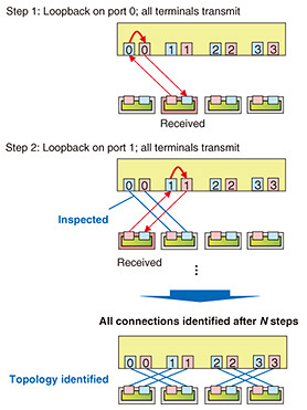
A straightforward inspection procedure is illustrated in Fig. 14. With this method, a loopback connection is established sequentially at each OCS port, and each terminal checks whether a signal is received. This approach enables accurate identification of fiber connectivity. However, as the number of terminal-connected fibers N increases, the number of required inspection operations grows linearly. Therefore, this naive approach does not scale to large systems.
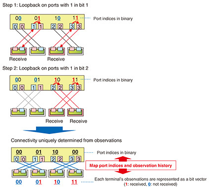
To address this issue, we present a more efficient fiber-verification method for terminal–OCS links. The key idea is to design loopback configurations systematically at each inspection step. Specifically, as shown in Fig. 7, OCS ports are indexed from left to right using binary numbering. At the l-th inspection step, loopback connections are established at ports, the l-th bit of which is equal to 1. Each terminal transmits a probe signal and observes whether the signal is received (Fig. 15).
By repeating this procedure for all bit positions, i.e., log2 N inspection steps, the entire fiber connectivity can be uniquely determined. Since the theoretical lower bound on the number of inspection operations for this problem is Ω(log2 N) [7], our verification method achieves near-optimal efficiency. In addition to topology verification, the quality of terminal–OCS fibers can be evaluated using a similar approach to that used for OCS–OCS fiber inspection, as described in Section 3.1.3. Specifically, each terminal i transmits a probe signal with power Ptx,i, and the received signal power Prx,i is measured after the signal returns through the loopback path. If the received power exceeds the threshold defined as
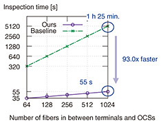
then the corresponding fibers are considered to be correctly connected and satisfy the required quality constraints. If the received power Prx,i is below the threshold In this manner, both the connectivity and quality of terminal–OCS fibers can be verified automatically and efficiently, provided that the terminals are equipped with optical monitoring functions such as DDM. This enables rapid and scalable inspection without manual intervention, even in large-scale OCS-based DCNs. 4.5 Practical significanceFigure 16 shows the inspection time required for terminal–OCS fiber verification as a function of the number of fibers in a two-stage TF-Clos network. Our verification method (Ours) was compared with the conventional sequential inspection method (Baseline).
In this evaluation, the number of fibers was varied from 64 to 1024, which corresponds to practical datacenter scales reported in hyperscale systems. The time required for a single inspection operation was assumed 5.0 seconds, corresponding to the switching time of a MEMS-based OCS [10]. The conventional method executed inspection sequentially, resulting in inspection time that increases linearly with the number of fibers. For example, when the number of fibers reached 1024, the total inspection time was approximately 1 hour and 25 minutes. In contrast, our method significantly reduced the number of required inspection steps by using a logarithmic probing strategy based on structured loopback configurations. As a result, the inspection time grew only logarithmically with the number of fibers. Even for 1024 fibers, the inspection could be completed in approximately 55 seconds. Overall, our inspection method achieved up to 93x faster inspection process compared with the conventional method. These results indicate that our method enables highly scalable and efficient fiber verification for terminal–OCS links, making it suitable for large-scale OCS-based DCNs. 5. ConclusionThis article presented a unified technical framework of our fiber-verification technologies for OCS-based DCNs. We first described an efficient inspection and certification method for fibers between OCS devices in hierarchical OCS-based DCNs. We then described a scalable topology and quality verification method for fibers between terminals and OCSs in single-layer OCS-based DCNs. The first method addresses the challenge of inspecting a very large number of inter-switch fibers without repeated tester reattachment while preserving correctness through path-uniqueness conditions and loss-aware certification. The second method addresses the different challenge of terminal-facing fiber verification in the presence of indistinguishable topology, DDM measurement error, and operational link-budget constraints. By combining signal-propagation models, link-budget-derived thresholds, and ambiguity-resolving probing algorithms, both methods achieve substantial improvements in verification efficiency while maintaining the correctness needed for production deployment. These technologies provide a practical basis for the reliable operation of large-scale OCS-based DCNs and will become increasingly important as future datacenters continue to scale in support of AI and other bandwidth-intensive applications. References
|
|||||||||||||||||||||