|
|||||||||||||||||||||||||||||||||
|
|
|||||||||||||||||||||||||||||||||
       |
Feature Articles: Environment and Energy Technologies Toward a Green Society Vol. 9, No. 2, pp. 31–36, Feb. 2011. https://doi.org/10.53829/ntr201102fa5 Development of SOFC Power Generation Module with High Electrical Generation EfficiencyAbstractThis article reports on the development of a 3-kW class solid oxide fuel cell (SOFC) power generation module being developed jointly by NTT, Sumitomo Precision Products Co., Ltd., and Toho Gas Ltd. as an industrial stationary power generation system. NTT has been developing cell materials, anode-supported cells, and SOFC stack technologies. The 3-kW class SOFC power generation module uses two 40-cell SOFC stacks. This module provided long-term and maximum electrical efficiencies of 56% and 59%, respectively. 
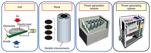
1. IntroductionWe are in the middle of the first commitment period of the Kyoto Protocol (2008–2012), and greenhouse gas reduction is an urgent worldwide problem. Developing fuel cells is one approach to greenhouse gas reduction. Fuel cells produce electric power via a direct reaction between oxygen and a fuel. Since a fuel cell has only one conversion step, its power generation efficiency tends to be higher than that of a thermal power generation plant. There are four main types of fuel cells. Among them, the solid oxide fuel cell (SOFC) can provide the highest power generation efficiency. It contains a solid oxide electrolyte made from a ceramic, which acts as a conductor of oxide ions at temperatures from 873 K to 1273 K. This ceramic material allows oxygen atoms to be reduced on its porous cathode surface by electrons and converted into oxide ions, which are then transported through the ceramic body to a fuel-rich porous anode zone where the oxide ions can react, giving out electrons to an external circuit. Generating electricity by transferring oxygen ion makes it possible to use many kinds of gases, such as town gas, gaseous kerosene, and biogas, as fuels that react with oxygen. Because an SOFC does not need large equipment such as a turbine to generate electric power, it can be used as a distributed generation power system with a low noise level. Since there is a great need for clean quiet distributed generation power systems, e.g., in hospitals, hotels, and sports facilities, the stationary power market has attracted considerable attention. We have been developing SOFCs to reduce the CO2 emissions produced by electric power use [1], [2]. An SOFC power generation system is composed of stacks of several cells in series and a module to maintain the temperature, as shown in Fig. 1. When electricity is generated with a power generation efficiency of more than 50% (lower heating value (LHV)) or more, the CO2 emissions can be reduced to less than those produced by existing electric power suppliers.
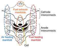
2. Cell/stack configurationWe had to develop a cell with high power generation efficiency, an electrolyte with high ion conductivity, and an electrode with high durability. We chose to use planar anode-supported cells consisting of a lanthanum nickel ferrite (LNF) cathode [3]–[5], a scandia-alumina stabilized zirconia (SASZ) electrolyte, and a nickel/SASZ anode [6], [7]. This cell has been shown to be able to provide a high power density of over 1.5 Wcm-2 and operate stably for thousands of hours. We developed stacks by combining power generation units, each of which is composed of an anode-supported cell with a diameter of 120 mm and interconnects made of corrosion-resistant ferritic stainless steel. The stack has not only a fuel feed manifold and an air feed manifold but also two fuel exhaust manifolds, as shown in Fig. 2 [8]–[10]. The exhaust manifolds will allow us to recycle unused fuel gas. In addition, it should also be possible to reduce the amount of CO2 exhaust to zero by collecting CO2.
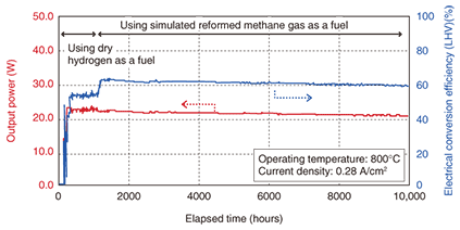
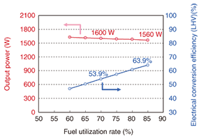
The behaviors of the output power and power generation efficiency of the power generation unit are shown in Fig. 3. When driven for 10,000 hours or more, the unit maintained a power generation efficiency of around 60% (LHV) [11]. The output power and the power generation efficiency of a stack composed of 40 cells in series are shown in Fig. 4. Output power of more than 1.5 kW was achieved with power generation efficiency of 63.9% (LHV) when the fuel utilization was 85%. By using this stack, we expect to be able to supply electric power stably with lower CO2 emissions than those of a business electric power supply or commercially available electric power supply.
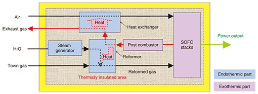
3. Construction of power generation moduleIf a lot of electricity is needed to maintain the operating temperature at over 873 K, the electric conversion efficiency of an SOFC power generation system will be inferior to that of an SOFC stack. To control the generation of, for example, Joule heat and endothermic heat, such as that produced by the reforming reaction, it is very important to maintain the operating temperature using little energy. NTT is developing the SOFC power generation module jointly with Sumitomo Precision Products Co., Ltd. (SPP) and Toho Gas Ltd. (THG) because THG has abundant experience operating fuel cells and SPP has both considerable experience and the technology needed for the heat exchanger [12]. Two stacks were integrated in a power generation module equipped with a steam generator, a steam reformer, a post combustor, heat exchangers and a start-up burner, surrounded by thermal insulators, as shown in Fig. 5. The module was designed so that the heat produced by the stacks and the post combustor was appropriately consumed by steam generation, the steam reforming reaction, and inlet gas heating. We used town gas as a fuel and air as an oxidant to evaluate the power generation performance. The water rate was determined so that the steam-to-carbon ratio was approximately 3. The current load was controlled by using external electronic load equipment.
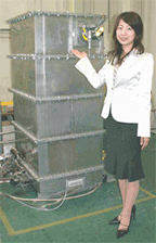
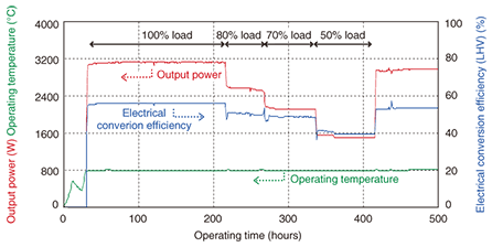
The developed module is shown in Fig. 6 and the output power, operating temperature, and power generation efficiency characteristics are shown in Fig. 7. The initial heating process lasted 10 hours and the thermal insulating behavior was observed after the start-up burner was turned off. The subsequent heating process with the burner raised the stack temperature to around 1073 K. The stacks started generating electrical power while the burner output was gradually decreased. A constant current load of 50 A was then applied to the stacks and the burner was turned completely off.
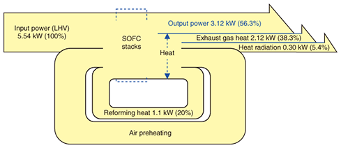
Thermally self-sustainable operation was achieved during operation for 200 hours with stable power output of 3.1 kW and power generation efficiency of 56% (LHV). Since the power generation efficiency was the same as that of the stack, as shown in Fig. 4, the module successfully controlled the heat with little energy consumption. In addition, we conducted a half-load power generation test and a standby test with no power generation, which resulted in isothermal operation of the stack. 4. Concluding remarksNTT, SPP, and THG have jointly developed an SOFC power generation module. The module can generate electrical power of over 3 kW and achieve power generation efficiency of more than 53% (LHV). With such high power generation efficiency, it is possible to reduce the CO2 emissions. However, for industrial power use, we must develop the balance of plant (BOP), which includes blowers, pumps, and a gas flow controller to supply the fuel and oxidant gas. Then, more electrical power with higher efficiency will be necessary to supply the electricity for these devices. One way to generate more electrical power with higher power generation efficiency is to use the exhaust heat from the module, which accounts for about 40% of the heat of the supply gas, as shown in Fig. 8. We believe that higher power generation efficiency will be obtained by using the exhaust gas heat with a gas turbine and also by recycling the unused fuel gas. Moreover, we plan to capture and store CO2 gas from the exhaust gas and develop an SOFC power generation system with zero CO2 emissions in the future.
References
|
||||||||||||||||||||||||||||||||