|
|||||||||||||||
|
|
|||||||||||||||
       |
Practical Field Information about Telecommunication Technologies Vol. 12, No. 2, pp. 57–61, Feb. 2014. https://doi.org/10.53829/ntr201402pf1 Lightning Damage and Mitigation in Telecommunication Access InstallationsAbstractIn this article, we introduce case studies of lightning damage in telecommunication access installations and a countermeasure against it. This is the twenty-first in a bimonthly series on the theme of practical field information on telecommunication technologies. This month’s contribution is from the EMC Engineering Group, Technical Assistance and Support Center, Maintenance and Service Operations Department, Network Business Headquarters, NTT EAST. Keywords: countermeasures, lightning damage, telecommunication access installations
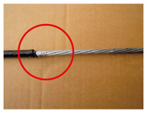
1. IntroductionLightning that directly strikes high-rise buildings and structures such as wind turbines or antenna towers usually causes lightning damage to telecommunication access installations adjacent to such structures. Particular cases include damage to messenger wires [1], discharge damage to telecommunication cable connections in splicing closures [2], and delamination of the surface of concrete poles (CPs) [3]. Damage to telecommunication installations due to lightning strikes may lead to interruptions in telecommunication services; accordingly, developing countermeasures against that possibility is an important challenge that requires further study. This article introduces examples of damage to telecommunication installations due to lightning strikes and explains the mechanism generating that damage. In addition, a construction method for improving robustness against lightning strikes (namely, configuring messenger wires in a particular way) is proposed, and the results of an experimental evaluation of the effectiveness of the proposed method are presented. 2. Cases of lightning damage to access installationsA direct lightning strike on a high-rise structure such as an antenna tower is accompanied by lightning damage to nearby telecommunication access installations. An example of damage caused by a lightning strike to the messenger wire used for fixing the telecommunication cable is shown in Fig. 1. Under the assumption that a large current flows as a result of such a lightning strike, it is expected that significant damage to the messenger wire will remain and that the messenger wire will degrade faster than usual.
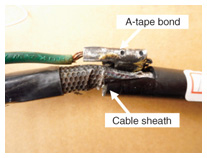
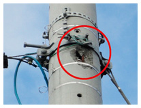
One phenomenon, namely, damage to a connection between a cable sheath and a ground wire bonded by aluminium tape (hereafter called an A-tape bond) in the splicing closure that connects telecommunication cables, is shown in Fig. 2. This phenomenon may potentially cause failure of the insulation between the core wires in the cable. Another phenomenon, that is, the surface damage of a CP, is shown in Fig. 3. This phenomenon makes it necessary to erect a new CP sometime in the future. Damage presumed to be caused by these phenomena related to lightning strikes often occurs on the telecommunication access installations located near high-rise buildings. Accordingly, understanding the mechanism that causes lightning damage to such installations and devising countermeasures against such damage are important targets of study.
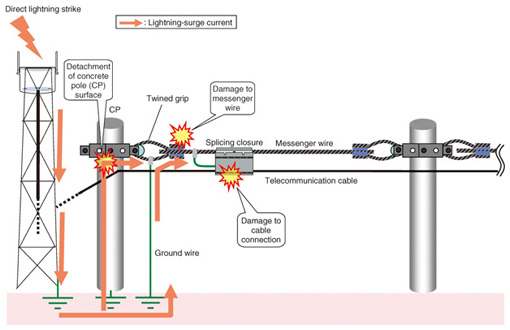
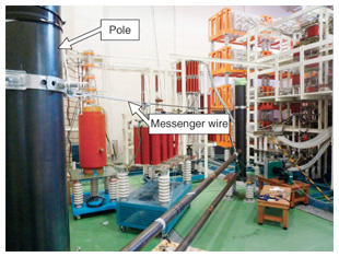
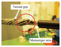
3. Mechanism of lightning damageThe configuration of a damaged telecommunication access installation and its surroundings is shown in Fig. 4. It comprises CPs, telecommunication cables, messenger wires, twined grips, support bands, and ground wires. The twined grips are generally used to connect the messenger wires to the CPs. Each twined grip is connected to a ground wire to ensure electrical-power safety and lightning protection. Moreover, as a safety measure, an aluminium-sheathed cable is used for the telecommunication cable, which is configured in such a manner that it is connected to ground at the point of connection with the cable inside the splicing closure.
The mechanism of the lightning damage that occurs in the above-described configuration is explained as follows. When the lightning directly strikes a high-rise building, a lightning-surge current is propagated through the building and flows to ground. Part of the surge current flowing to ground flows in the opposite direction, namely, up the ground line, as a backflow current. The surge current that flows into the ground wire then flows into the messenger wire via the twined grip. The energy generated by this surge current exceeds the surge capacity of the messenger wire, which is thereby damaged [1]. Furthermore, if the energy of the surge current flowing in the messenger wire exceeds the surge capacity of the A-tape bond, the connection of the cable sheath and the A-tape bond heats up and becomes damaged [2]. In addition, the flow of the lightning-surge current to ground raises the electrical potential of the ground. As a result, an overvoltage is applied to the concrete medium between the support bands and reinforcing bars of the CPs. As a result of this overvoltage, the insulation provided by the concrete breaks down, and the concrete surface of the CPs detaches in places [3]. 4. Experiment to evaluate lightning-surge capacity of messenger wireWe verified the damage mechanism of the messenger wire by applying lightning-surge current simulating a direct lightning strike to the messenger wire and then evaluated the result [1]. The configuration of the experimental facility is shown in Fig. 5. The messenger wire in this figure is made of high-corrosion-resistance steel (18CR) with a diameter of approximately 5 mm. The lightning surge is applied by an impulse generator (IG). The output and return terminal of the IG are respectively connected to the twined grip and the messenger wire via a ground wire. A 10/350-μs current waveform regulated as a direct lightning strike was used in accordance with lightning-surge experiment standard IEC 61312-3 [4].
Examples of the experimental results are shown in Figs. 6 and 7. A spark discharge is shown in Fig. 6, and traces of the electrical discharge remain on the messenger wire as shown in Fig. 7. The electrical discharge occurs near the connection between the messenger wire and the twined grip, and the peak value of the current wave at the time of discharge is 23.8 kA.
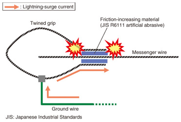
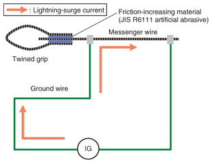
In order to prevent a disconnection at the twined grip and the messenger wire, friction-increasing material (artificial abrasive JIS R 6111) is coated on the internal surface of the spiral part of the connection (Fig. 8). Because of that coating, a gap is formed in the connection, and that gap is thought to make it easier for spark discharge to be generated by the surge current. Consequently, it is thought that damage to the messenger wire such as corrosion of the wire itself and degradation of the zinc coating will remain, and the messenger wire will deteriorate faster than normally expected.
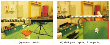
The peak current value of the direct lightning strike is generally several dozen kiloamperes (kA). During the winter in the regions along the Sea of Japan, however, on rare occasions, lightning strikes with current-wave peaks exceeding 100 kA have been measured. When such a large current flows in the messenger wire, the kind of damage that occurs also depends on the duration of the current flow. In this experiment, we confirmed the phenomenon in which the zinc-aluminium-alloy coating on the messenger wire melted and dripped onto the ground (see Fig. 9.).
5. Study of countermeasures against lightning damageMuch research on lightning damage has been done in order to develop countermeasures to it [5], [6]. The results of the evaluation of the lightning strike capacity described above were used to determine a configuration method that mitigates the deterioration of the messenger wire. In particular, a method of connecting the ground wire to the main messenger wire on the external side of the twined grip was devised, as shown in Fig. 10, and its effectiveness was evaluated experimentally.
Constructing the connection in this way causes the surge current flowing in from the ground wire to flow into the messenger wire without passing through the connection between the messenger wire and the twined grip. As a result, it is possible to avoid the discharge phenomenon that occurs near the connection between the messenger wire and the twined grip. The experimental results indicated that the peak value of the current wave during the spark discharge was 36 kA. This result confirms the effectiveness of the configuration method; that is, applying this method increases the surge capacity by approximately 1.5 times (spark discharge occurs at 23.8 kA) at little extra cost. 6. ConclusionThis article described cases of lightning damage occurring in telecommunication access installations located near high-rise structures. Additionally, a countermeasure to the lightning damage occurring at the messenger wire was proposed based on the results of an evaluation experiment. The results of this study are summarized as follows. A spark discharge due to the lightning surge is generated near the connection between the messenger wire and the twined grip. To alleviate deterioration of the messenger wire, a method of connecting the connection point of the ground wire with the main messenger wire was proposed as a countermeasure and confirmed to be effective. From now on, we plan to follow the proposed procedure in the design and installations maintenance departments. Lightning damage occurs at various points in telecommunication installations. At the NTT Technical Assistance and Support Center, we aim to provide trouble-free communication services and to reduce maintenance work that results from lightning damage. We are therefore actively proposing effective and economic lightning-damage countermeasures based on on-the-spot investigations, developing lightning-resistant products for telecommunication installations (including telecommunication equipment), and promoting activities to popularize technologies through technical seminars. References
|
||||||||||||||