|
|||||||
|
|
|||||||
       |
Feature Articles: Current Status of Technology Development Toward Energy-saving––For Continuous Telecommunications Infrastructure Connections 24/7 Vol. 12, No. 3, pp. 37–43, Mar. 2014. https://doi.org/10.53829/ntr201403fa6 EMC Technology that Protects Network Equipment from Electromagnetic ProblemsAbstractNTT has prohibited the use of wireless devices in telecommunications equipment rooms to prevent interference from such devices causing serious equipment failures. However, there is a growing call to improve the efficiency of maintenance work in these rooms by establishing conditions for the safe use of wireless devices. Demand is also growing to make networks more resistant to natural disasters such as lightning, damage from which has been increasing in recent years. This article introduces our activities that address these issues. Keywords: EMC, in-house standards, TR
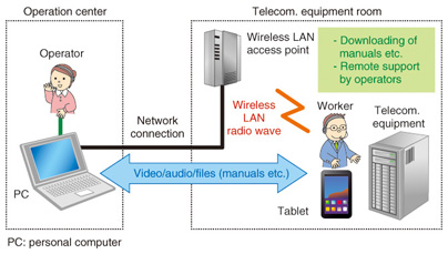
1. IntroductionThe NTT Group aims to build a telecommunications infrastructure that provides continuous connections 24 hours a day and has therefore been working to establish an efficient maintenance framework and to reduce the number of faults that occur. In addition, it has been implementing measures to reduce the energy consumption and CO2 emissions of telecommunications equipment, power supply systems, air-conditioning systems, etc., and measures to reduce operating expenses (OPEX) in order to provide high-quality telecommunications services at low prices. The use of electromagnetic compatibility (EMC) technology is being applied to support these efforts [1], [2]. The purpose of EMC technology is to provide reliable telecommunications services by preventing the equipment that makes up a telecommunications infrastructure from radiating electromagnetic waves that might interfere with other equipment and also from being affected by electromagnetic waves from other equipment, or even from lightning. This article introduces some recent development activities in the area of EMC. Specifically, it introduces activities to improve maintenance efficiency by enabling wireless devices to be used safely in telecommunications equipment rooms, and activities to reduce the number of faults caused by lightning. 2. Activities to enable the use of wireless devices in telecommunications equipment rooms2.1 Background to this studyToday NTT prohibits, in principle, the use of wireless devices in telecommunications equipment rooms in order to avoid the risk of wireless devices interfering with telecommunications equipment and causing a serious failure. However, NTT is also studying a new operation and maintenance procedure that makes use of convenient tablet-type terminals equipped with wireless local area network (LAN) access capability, which have become widespread in recent years. An example of maintenance work carried out using a tablet is shown in Fig. 1. The worker in the telecommunications equipment room downloads procedure manuals to a tablet and conducts maintenance work with assistance from an operator at a remote site. The worker and operator can communicate with each other using both audio and video, and it is easy to confirm the required tasks. Therefore, erroneous operations can be avoided, and work efficiency can be improved.
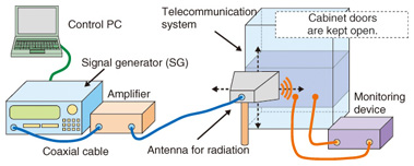
To allow this type of maintenance work, it is necessary to enable a wireless LAN to be used in telecommunications equipment rooms. However, as mentioned earlier, use of wireless devices is currently prohibited. Removal of this restriction will require the establishment of conditions under which radio waves from a wireless LAN do not affect telecommunications equipment, and the development of a guideline for the safe use of wireless devices. 2.2 Establishing conditions for safe use of wireless devicesWith the aim of establishing conditions for the safe use of wireless devices in telecommunications equipment rooms and thereby enabling efficient maintenance work, in July 2011, NTT Energy and Environment Systems Laboratories and the Technical Assistance and Support Center, Maintenance and Service Operation Department, Network Business Headquarters, NTT EAST, took the initiative to create a Working Group on the Use of Wireless Devices in Telecommunications Equipment Rooms. This Working Group (WG) consisted of members from various companies in the NTT Group, and it initiated a study to measure the effect of wireless LAN on telecommunications equipment and to establish conditions for the safe use of wireless devices. The WG focused on the following areas: (1) Measuring how a wireless LAN affects telecommunications equipment The extent of the effect imposed by radio waves emitted from a wireless LAN depends greatly on a telecommunications system’s immunity to interference. However, this immunity differs from system to system. Therefore, we measured the effect of radio waves from a type of wireless LAN that maintenance staff in the field have asked to use. The test system used for this measurement is shown in Fig. 2. The signal generator generates and amplifies wireless LAN signals, which are radiated towards telecommunications systems from an antenna. The test to evaluate the immunity of a system to external radio waves is called a radiation immunity test. The required basic test conditions are specified in ITU-T (International Telecommunication Union, Telecommunication Standardization Sector) Recommendation K.48. However, evaluations based on the test conditions compliant with this recommendation face the following problems:
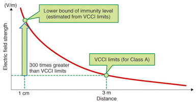
a) Since the recommendation uses a narrow-band AM (amplitude modulation) signal (1 kHz, 80%) as the test signal, the extent of interference measured based on this recommendation is likely to be different from that from the broadband signals of a wireless LAN. b) The specified test electric field strength level does not necessarily match the electric field strength experienced when a wireless device is located close to a telecommunications system. These problems were solved as follows. (a) The test signals used simulated signals from a wireless LAN (orthogonal frequency division multiplexing), and measurements were made in the 2.4-GHz and 5.2-GHz bands, which are standard for a wireless LAN. (b) The test level was set at the electric field strength that exists when a telecommunications system is 1 cm away from a wireless LAN (18 V/m). We tested about 90% of all the telecommunications systems in use in telecommunications equipment rooms today and checked whether alarms were generated, or whether any degradation in performance (such as an increase in transmission loss) arose when test signals were applied. From the results of this test, we were able to specify the minimum distance between a wireless LAN and a telecommunications system at which the telecommunications system is not affected by radio waves from the wireless LAN and thus, where wireless devices can be used safely. (2) Dealing with systems for which testing is difficult Item (1) above described how we used a test system to radiate radio waves towards actual telecommunications systems, how we checked whether the radio waves affected telecommunications systems or not, and how we derived conditions for using wireless devices. However, in reality, most telecommunications equipment rooms accept collocation; that is, they also house telecommunications systems operated by non-NTT providers. Therefore, it is necessary to establish conditions for using wireless devices without fear of affecting the telecommunications systems of other providers, thereby also enabling these providers to use wireless devices. Setting up a test system that could be used to measure interference with other providers’ systems was difficult, so it was necessary to devise an alternative means. To solve this problem, we studied a method of estimating the lower bound of the immunity of these systems. At present, NTT’s in-house standard requires that the electromagnetic interference level of telecommunications systems installed in telecommunications equipment rooms satisfy the requirements for Class A of the technical standard specified by VCCI (the Voluntary Control Council for Interference by Information Technology Equipment). Class A specifies that the electric field strength measured at a 3-m distance from telecommunications systems must be 76 dBμV/m or lower from 1 to 3 GHz, and 80 dBμV/m or lower from 3 to 6 GHz. The electric field strength is roughly inversely proportional to the distance from the radio wave radiating point. Therefore, the electric field strength at a point 1 cm away from a telecommunications system is about 300 times stronger than that at a point 3 m away from the system. Telecommunications systems in telecommunications equipment rooms work well even when they are installed close to each other. This implies that telecommunications systems in telecommunications equipment rooms have an immunity that is higher than the electric field strength of the disturbance wave radiated by adjacent telecommunications systems (about 300 times higher than the level specified in the VCCI standard). This fact makes it possible, as shown in Fig. 3, to estimate the lower bound of the immunity at a point 1 cm from a telecommunications system based on the electric field strength of electromagnetic disturbing waves (VCCI-specified level) at a point 3 m away from a telecommunications system. Determining the distance at which this estimated level becomes equal to the electric field strength of radio waves from a wireless LAN makes it possible to derive conditions under which radio waves from a wireless LAN do not affect telecommunications systems―in particular, systems of other providers that cannot be easily tested.
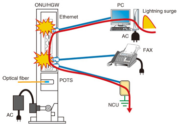
Using (1) the conditions for use of a wireless LAN derived from measuring the effect of radio waves from a wireless LAN on telecommunications systems, and (2) conditions for use of a wireless LAN derived from estimating the immunity level of telecommunications systems, NTT has developed a guideline that establishes the conditions under which wireless devices can be used safely in telecommunications equipment rooms, and thus has been improving the efficiency of maintenance work. 3. Activities to reduce the number of faults caused by lightning in an optical access service3.1 Current state of faults by lightningMost faults in an optical access service that are caused by lightning occur at optical access terminals such as optical network units (ONUs) and home gateways (HGWs), which are installed inside buildings owned and managed by customers. This is because it is difficult for NTT to implement protective measures against lightning inside buildings owned and managed by its customers. In contrast, telecommunications systems in NTT communication centers and datacenters have been protected from lightning by connecting these systems to ground and using lightning-resistant transformers in power supply systems. For example, Japan’s low-voltage power distribution network uses TT (Terre-Terre, or earth-earth) grounding, which does not use protective grounding conductors from the distribution network. Therefore, it is difficult to ground optical access terminals. In addition, since the configuration of local networks to which optical access terminals are connected has grown more diverse and complicated, lightning faults occur through different mechanisms, which were unknown until recently. NTT has been working on a solution to this problem by carrying out activities to reduce the number of faults that occur, particularly those occurring in optical access terminals because of lightning, in order to provide reliable telecommunications services. The mechanism of how lightning damages optical access terminals is explained below, and measures to prevent such damage are also described. 3.2 Mechanism of fault occurrence in optical access terminalsTo find out how lighting damages optical access terminals, it is necessary to determine the parts of the optical access terminal that are damaged and the path through which a lightning surge flows. For this purpose, in June 2011, NTT Energy and Environment Systems Laboratories and the Technical Assistance and Support Center, Maintenance and Service Operation Department, Network Business Headquarters, NTT EAST, took the initiative to create within the NTT Group a Working Group on Protection from Overvoltage, and began collecting ONUs/HGWs that had been damaged by lightning and analyzing the faulty parts. This analysis has revealed that lightning-induced faults that involve damage to both the POTS (Plain Old Telephone Service) port and the Ethernet port have been increasing in number. The path through which a lightning surge flows and the mechanism of occurrence of lightning-induced faults are described below and shown in Fig. 4.
(i) A lightning strike raises the electric potential of the ports of all devices within the building. (ii) Most facsimile machines and network control units (NCUs, i.e., units used to remotely control gas meter reading etc.) that are connected to the POTS port of the ONU/HGW have built-in surge protective devices (SPDs). When lightning strikes, the SPD operates and, as a result, the potential of some communication lines and power supply lines becomes equal to the ground potential. (iii) A potential difference arises between the POTS port, whose potential is equal to the ground potential, and the other ports (the Ethernet port connected to a PC in Fig. 4), which remains at the raised potential. (iv) This difference in potential causes an insulation breakdown between the Ethernet port and the POTS port, and both of these ports are damaged simultaneously. This type of fault would not occur if the telecommunications device concerned had only a telephone port and an AC (alternating current) power port, as in the case of a conventional telephone. However, with the spreading use of optical access terminals such as ONUs/HGWs―which have multiple ports for connection to different devices and are thus susceptible to simultaneous damage to two ports―cases of lightning-induced damage are increasing in regions where lightning is frequent. 3.3 Overvoltage resistibility test for existing optical access terminalsTo reduce the number of optical access terminals damaged by lightning, it is necessary to determine the technical requirements (resistance to lightning-induced overvoltage, testing method, etc.) for these terminals based on the above-mentioned mechanism of fault occurrence, and to develop terminals that satisfy these requirements. (1) Revisions to technical requirements (TRs) concerning resistance to overvoltage
NTT has been complying with existing TRs concerning overvoltage resistibility (hereinafter referred to as overvoltage TR) of telecommunications systems. However, they do not embrace the technical requirements necessary to prevent the occurrence of faults by the above-mentioned mechanism. Therefore, we have established TRs for the Ethernet port of an optical access terminal, which is the port that provides a path for a lightning surge to reach the terminal, and have revised the overvoltage TR accordingly. Specifically, we have added requirements for overvoltage resistibility between the Ethernet port and the POTS port as well as a method of measuring this. Since lightning-induced faults can occur between multiple Ethernet ports by the same mechanism, we have also added requirements for overvoltage resistibility between Ethernet ports and a method of measuring it. (2) Determining how to enable optical access terminals to satisfy the overvoltage TR
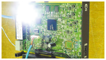
The output device of an ordinary Ethernet port is protected by an isolating transformer, called a pulse transformer, which provides isolation from the external wires connected to the network equipment that suffered from overvoltages. The Ethernet port of the standard ONU/HGW in use today also has a pulse transformer built into it. However, pressure is mounting to downsize the ONU/HGW; consequently, it is not easy to satisfy the requirements for both high packaging density and high dielectric strength simultaneously. We conducted a lightning surge test on existing ONUs/HGWs and found that a discharge occurs at a voltage lower than that specified for overvoltage resistibility in the overvoltage TR. When overvoltage was applied to a POTS port and an Ethernet port of the ONU/HGW, the bright spot shown in Fig. 5 was observed. The bright spot indicates a breakdown occurred at the pulse transformer.
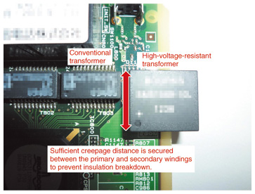
One way to strengthen the overvoltage resistibility is to increase the distance between the primary and secondary windings of the pulse transformer. A pulse transformer with an increased insulation distance is compared with an existing pulse transformer in Fig. 6.
To verify this solution, we conducted an overvoltage resistibility test, in the manner used in Fig. 5, with a test terminal on which a pulse transformer with an increased insulation distance had been mounted. The test confirmed that no discharge occurred, indicating that the overvoltage resistibility was improved. The NTT Group will continue to study a method of mounting the improved transformer on the ONU/HGW and also an alternative method of attaching an external lightning-resistant component to Ethernet ports. Improving the overvoltage resistibility of optical access terminals will help to reduce the number of lightning-induced faults. We will continue to pursue activities to reduce such faults in the future. 4. ConclusionThis article has introduced some of the recent developments in the area of EMC technology to protect network equipment from electromagnetic problems. Specifically, it has introduced activities to enable wireless devices to be used safely in telecommunications equipment rooms, and activities to reduce the number of faults caused by lightning. We have developed a technique to determine conditions for using a wireless LAN while ensuring that the radio waves it radiates do not affect the surrounding telecommunications systems, and a technique to determine conditions for using a wireless LAN even in cases where it is difficult to conduct tests with actual telecommunications systems. These techniques have made it possible to use a wireless LAN safely in telecommunications equipment rooms, even those where telecommunications systems of non-NTT providers are collocated. Enabling the use of a wireless LAN in a telecommunications equipment room under these conditions will make it possible to improve the efficiency of a variety of maintenance tasks and thereby to reduce OPEX. We also introduced the results of analyzing a new mechanism in which a lightning strike causes a fault between the POTS port and the Ethernet port of an optical access terminal, and activities to reduce the number of lightning-induced faults. Looking ahead, we will continue to pursue activities to reduce the number of lightning-induced faults, thereby leading to fewer dispatches of maintenance staff in the field and contributing to the reduction of OPEX. References
|
||||||