|
|||||
|
|
|||||
       |
Practical Field Information about Telecommunication Technologies Vol. 13, No. 2, pp. 40–45, Feb. 2015. https://doi.org/10.53829/ntr201502pf1 Recent Case Studies of Packet Capture and Analysis ―Use of Captured-data Analysis Support Tool―AbstractThis article introduces case studies involving packet capture and analysis using a support tool. This is the twenty-seventh of a bimonthly series on the theme of practical field information on telecommunication technologies. This month’s contribution is from the Network Interface Engineering Group, Technical Assistance and Support Center, Maintenance and Service Operations Department, Network Business Headquarters, NTT EAST. Keywords: IP-related faults, packet capture, captured-data analysis support tool
1. IntroductionThe volume of Internet protocol (IP)-related data communications has been increasing thanks to the recent proliferation and increasing sophistication of IP broadband access services typified by NTT’s FLET’S HIKARI NEXT and the rise of social network services and other novel services. The functionality of routers and terminals installed in homes has consequently been advancing, but this has been accompanied by increasingly complicated IP faults. As a result, there has been an increasing number of cases in which the conventional approach of dealing with a fault by simply replacing faulty equipment has not been effective. In response to this situation, techniques for identifying the causes of such faults have been promoted. These techniques obtain (capture) a large volume of packets transmitted between IP devices through the use of our gigabit-compatible protocol checker [1] or a similar tool and analyze the state and content of communications. However, with popular software for packet analysis such as Wireshark, the operations needed to identify the packets that are causing the fault from a large volume of captured data can be quite complicated and extremely time-consuming. Maintenance personnel must also learn how to use such analysis methods, which means that the analysis results can depend greatly on the maintenance personnel’s individual skills. To address these problems, we have developed and begun using a captured-data analysis support tool equipped with functions for supporting batch input and analysis of a large volume of captured data so that the causes of complicated IP faults can be quickly uncovered. We describe here some recent case studies of packet capture and analysis using this tool. 2. Overview of captured-data analysis support toolThe captured-data analysis support tool consists of software that inputs data captured in the pcap/pcapng packet-capture format and displays the results of analyzing that data. This tool has an analysis section and a display section with a total of five functions, as shown in Fig. 1.
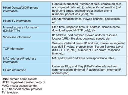
(1) Captured-data analysis function This function analyzes captured data and is the core of this software. It is capable of analyzing several gigabytes of data divided into multiple files all together. The display section presents the results of this analysis using the summary display function ((3) in Fig. 1), graph display function (4), and log display function (5). Maintenance personnel can re-examine analysis results for certain data without having to perform the analysis again by simply inputting that data into the display section. (2) Time-offset output function This function changes the timestamp given to each captured packet. This is a useful function if the user wishes to correct the timestamps of captured data whose times are offset from the actual time. (3) Summary display function This function displays the results of analysis performed by the captured-data analysis function. It can display various types of service- and protocol-related information as listed in Table 1. Each type of summary information can be subjected to full-text searches, making it easy to display a portion of the analysis results that are of interest to the maintenance personnel and to check individual packets in unison with Wireshark.
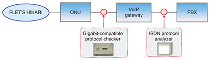
(4) Graph display function This function can display multiple time series simultaneously. Specifically, it can simultaneously compare multiple time series such as the number of simultaneous IP phone calls, the estimated number of network address and port translation (NAPT) tables, and traffic volume, which is not possible with other types of software such as Wireshark. (5) Log display function This function prepares logs from information in communication packets recorded in routers and other communication devices and displays those logs. It can display that information in classes; for example, log data that may indicate the cause of a fault can be labeled as a warning, and other data that reflect the process flow needed for analysis can be labeled simply as information. 3. Case studies of using the captured-data analysis support tool to identify faults3.1 Call is suddenly disconnected in IP phone service3.1.1 Fault descriptionA customer using an IP phone service at a call center reported that calls would suddenly be disconnected several times a day during peak calling periods. The problem persisted despite replacing the VoIP (voice over IP) gateway. 3.1.2 Inspection methodWe installed the gigabit-compatible protocol checker between the ONU (optical network unit) and the VoIP gateway to collect data on call-control and voice packets and installed an ISDN (integrated services digital network) protocol analyzer between the VoIP gateway and the PBX (private branch exchange) to collect data on call control (Fig. 2).
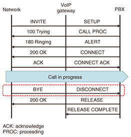
3.1.3 Inspection resultsA check of the call control sequence at the time of a cutoff event indicated that the call had been disconnected in a normal manner from the network side (Fig. 3). It was also found on checking voice packets (RTP/RTCP: real-time transport protocol/real-time transport control protocol) that the VoIP gateway had transmitted no RTCP packets several tens of seconds before the normal disconnection.
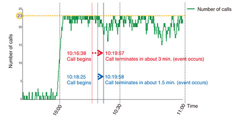
3.1.4 Cause of faultOn the basis of the inspection results described in 3.1.3 above and the customer’s report stating that the event would occur during peak calling periods, we checked calling conditions using the captured-data analysis support tool (Fig. 4) and found that the event would typically occur when the number of calls had risen dramatically, which occurred just after 10:00 AM. We therefore considered the possibility that the non-transmission of RTCP packets from the VoIP gateway was related in some way to the large number of calls.
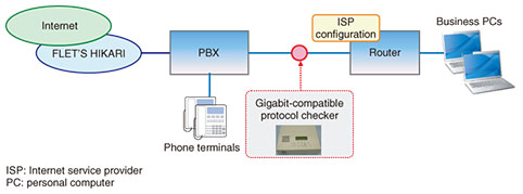
3.1.5 Countermeasure and effectWe shared this information with the developer of this VoIP gateway, which proposed as a countermeasure that the gateway equipment be replaced with its most recent version that had higher performance. The problem disappeared upon doing so. 3.2 Internet is disconnected3.2.1 Fault descriptionA customer reported experiencing trouble connecting to the Internet once or twice a week when starting work in the morning but said that the problem would disappear on its own in about ten minutes. The customer was also a subscriber to an IP phone service that functioned normally at the time of this event. 3.2.2 Inspection methodWe installed the gigabit-compatible protocol checker between the PBX and router and captured data for a one-week period (Fig. 5).
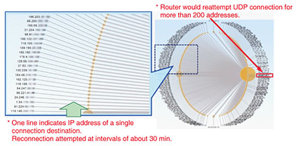
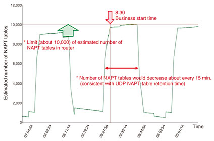
3.2.3 Inspection resultsWe analyzed the data captured in this way using the Cascade Pilot software developed by Riverbed Technology and found that the router was attempting to make UDP (user datagram protocol) connections for more than 200 IP addresses and was performing unauthorized-access actions (Fig. 6). We also checked the number of estimated NAPT tables using the captured-data analysis support tool and found that the number of connections would approach the 10,000 limit of the router about every 15 minutes (Fig. 7).
3.2.4 Cause of faultWe speculated that the router’s NAPT tables were becoming depleted through unauthorized access from the router’s LAN (local area network) side, and that the Internet was inaccessible by computers connected at that time. 3.2.5 Countermeasure and effectBecause we captured data on the WAN (wide area network) side of the router in this inspection, we were not able to isolate the terminal that was generating such a large amount of data traffic. Maintenance personnel explained the analysis results to the customer and requested that any business PCs that were infected by a virus be removed from the LAN. The customer complied with the request, and the fault subsequently disappeared. 4. ConclusionThis article presented recent case studies of packet capture and data analysis using our captured-data analysis support tool. Going forward, the Technical Assistance and Support Center is committed to identifying the causes of faults through packet capture using a variety of tools and to contribute to the early resolution of increasingly complicated IP-related faults. Reference
|
||||