|
|||
|
|
|||
       |
Practical Field Information about Telecommunication Technologies Vol. 15, No. 8, pp. 55–60, Aug. 2017. https://doi.org/10.53829/ntr201708pf1 Metallic Cable Fault Location Search TechnologyAbstractThis article describes faults that occur in the core wire of metallic cables and the methods used to locate them. This is the forty-first article in a series on telecommunication technologies. This contribution is from the Access Engineering Group, Technical Assistance and Support Center, Maintenance and Service Operations Department, Network Business Headquarters, NTT EAST. Keywords: metallic cable, open-circuit fault, insulation fault
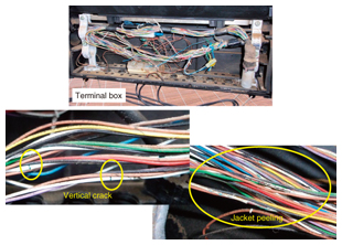
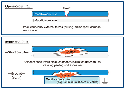
1. IntroductionMassive amounts of metallic cables were installed outside NTT offices during the era when the number of fixed-line telephone subscribers was increasing. In recent years, however, faults in the core wire of these cables have begun to appear as a result of aging. The current approach at maintenance hubs is to conduct repairs whenever such a fault is discovered. However, although metallic cable facilities are expected to gradually decrease in number with the shift toward an optical-fiber cable network, it cannot be assumed that all metallic cables will soon be gone. To prevent circuit problems, it is important to quickly estimate the location of faults in metallic cables and deal promptly with those faults. 2. Metallic cable faultsFaults in metallic cables include cross (short-circuit) faults, insulation faults, and ground faults due to factors such as humidity or cable submersion in water (Photo 1). Such faults can cause circuit malfunctions such as noise and interrupted communications (Fig. 1).
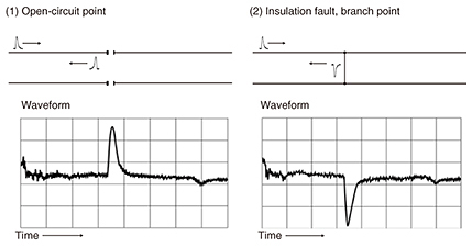
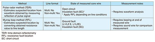
The conventional response to the occurrence of such a fault has been to search for the fault using a labor-intensive technique by which maintenance personnel open up a cable-connection point in the field, determine whether the fault lies in the interval above that point (facility-center side) or below that point (customer side) using a device such as an insulation-resistance meter, and repeat that process until the fault location is isolated. 3. Present methods of estimating fault locationA typical method of evaluating the soundness of a metallic cable is to measure characteristics such as insulation resistance, electrostatic capacitance, loop resistance, and extraneous voltage/current using testers and testing tools. However, it is not standard to estimate a fault location using a measurement device designed for that purpose in the field. Measurement devices for estimating fault locations in metallic cables have actually existed for some time. However, obtaining estimations with such a device requires a sufficient understanding of measurement methods, knowledge of the state of the core wire being measured (open-circuit, short-circuit, or ground fault), and selection of an appropriate measurement method depending on the state of the core wire, line configuration, and other factors. These requirements have made fault-location operations difficult in practice. 4. Fault-location searching methodsWe introduce here two key methods for estimating fault locations in metallic cables using commercially available devices. (1) Pulse radar method This is an effective measurement method for searching out fault locations for open-circuit and short-circuit faults. A pulse voltage is applied to the core wire, the round-trip propagation time of the pulse voltage reflecting off the abnormal point is graphed, and the distance to the abnormal point is estimated. Specifically, this method derives the distance to the fault location from the product of the round-trip propagation time and the propagation speed of the pulse voltage, the latter of which depends on the type of cable. For example, propagation speed is 96 m per microsecond in the case of colored code polyethylene (CCP) conductors with a diameter of 0.4 mm. A property of a pulse signal is that it will be reflected when encountering an impedance mismatch in the cable. The point where such an impedance mismatch occurs may indicate an open-circuit point, insulation-fault point, or branch point in the cable. An open-circuit point corresponds to a state of high impedance and is therefore displayed as an upward waveform. An insulation-fault point or branch point, meanwhile, corresponds to a state of low impedance and is therefore displayed as a downward waveform (Fig. 2).
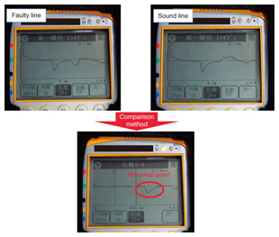
With this method, it may be difficult to read an open-circuit waveform depending on the diameter of the core wire and the configuration of the target line. The comparison method has been found to be effective in such cases. This method simultaneously connects a faulty line and a sound line under identical conditions to a measurement device and displays the difference between the obtained pulse waveforms to clarify the fault location (Photo 2).
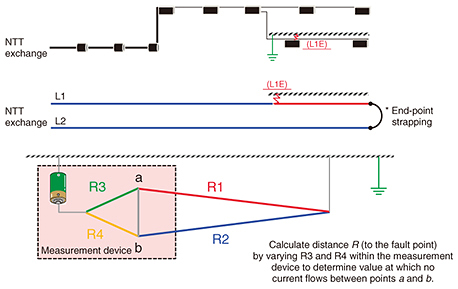
A weak point of the pulse radar method is that reflection from each end point (open end) of each branch in a branched configuration is the same as that from an open-circuit point. This may complicate the pulse waveform graph, preventing the fault location from being displayed (inferred). Therefore, the pulse radar method is an effective means of searching for the location of an open-circuit or short-circuit fault in a line with no branches. (2) Murray loop method This is an effective measurement method for finding the location of a short-circuit fault or ground fault. The principle of the Wheatstone bridge is applied to estimate the location of a fault point on the basis of line resistance values (Fig. 3). The length of the measured line must be input to the measurement device beforehand so that resistance can be read as distance and so the end point of the measured line can be strapped (looped) to form a measurement circuit.
While measurement in the case of a branched line is relatively difficult for the pulse radar method described above, the Murray loop method can be used to estimate the fault location even on a line with branches. For example, when measurements are conducted when the end point of the main line is strapped, and given that the fault point lies on the branch line, the location (distance) at which the branch on the main line begins would be measured as the fault point. However, if that location were assumed to be sound, the line interval branching from that position would become suspect. In this way, the Murray loop method is an effective method for finding fault locations regardless of branching in the case of short-circuit or ground fault. The pulse radar method and Murray loop method are compared in Table 1.
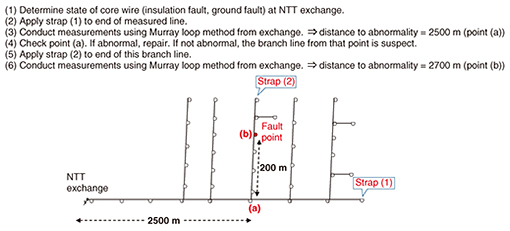
5. Example of searching for fault locationWe present here an example of locating a fault in a metallic cable (Fig. 4). First, it is important to confirm the present state of the core wire to be searched, that is, whether the fault is of the open-circuit, short-circuit, or ground type, so that the most appropriate fault location search method can be selected. If the core wire in question is in a state other than an open-circuit, short-circuit, or ground fault, care should be taken since such a state is not suited to fault location searching using a measurement device.
Next, the fault is evaluated to determine whether it occurred in the underground interval or the aerial interval. If it can be determined to lie on the underground interval, the position is identified and the search is completed. However, if it is judged to lie on the aerial interval and branch lines exist, the procedure is to obtain measurements using the Murray loop method after strapping any one of the branch lines on the main line to determine a fault point. Then, if that position after checking turns out to be sound, the branch line connected to that point is suspect. If that branch line itself has no branching, the pulse radar method can be used to obtain measurements from the start point of that branch. On the other hand, if the branch line itself includes branching, its end point can be looped and the Murray loop method used to search again for the fault location. The fault location can be found in this way. In an aerial interval, metallic cables are said to be easily affected by external factors such as wind, rain, and ultraviolet rays that can give rise to many faults. Since it is normal for the aerial interval of cabling to have branch lines, an appropriate approach would be to use the Murray loop method to perform rough interval identification and narrow down the interval, and to use the pulse radar method to isolate the fault position. In other words, it is more effective to use multiple methods in a composite manner instead of being tied to a single method. 6. ConclusionThis article introduced techniques for quickly estimating fault locations in metallic cable with the aim of preventing circuit failures. While leveraging the knowledge and expertise it has gained in the maintenance and operation of diverse facilities, the Technical Assistance and Support Center will continue to provide technology consultations, reply to support requests, and promote technology dissemination for all concerned parties in order to strengthen the reliability of access network facilities. |
||