|
|||
|
|
|||
       |
Feature Articles: Smart Infrastructure Facility Management Vol. 19, No. 1, pp. 68–71, Jan. 2021. https://doi.org/10.53829/ntr202101fa11 Evolving MMS from 3D Measurement of Road Area to Facility Inspection—Diagnosing Wear in Millimeters and Deterioration in Terms of Rust, Stains, and CracksAbstractA mobile mapping system (MMS) measures surrounding structures (including roads) in three dimensions and creates a database based on the obtained information. Measurement equipment mounted on a vehicle mainly consists of devices for measuring the position of the vehicle and measuring around the vehicle three-dimensionally (laser devices are the mainstream). Efforts by NTT Infrastructure Network Corporation (NTT InfraNet) to address issues concerning an MMS are introduced in this article. Keywords: MMS, GNSS, stereo camera
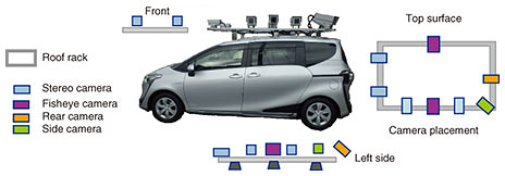
1. Overview of our MMSThe key feature of the mobile mapping system (MMS) developed by NTT Infrastructure Network Corporation (NTT InfraNet) is that it uses stereo cameras, which enables three-dimensional (3D) measurement using a camera-only photography function. For this function, we developed a technology for synchronous shooting involving multiple cameras, enabling highly accurate measurement (Fig. 1). By improving the resolution of still-image shooting, which must satisfy a frame rate of 10 frames or more per second, we have been able to evolve an MMS (which is mainly used for measuring the shape of structures) to beyond its normal applicable area, namely, to a level at which it can be used to inspect the deterioration and wear of facilities such as manholes to the millimeter.
The main issues concerning the practical use of an MMS are as follows: reducing the cost of equipment and vehicles while improving accuracy; eliminating calibration running before and after measurement; reducing interruptions for stabilizing satellite positioning during measurement; enabling drivers and system operators to do their work without expert skills; and improving efficiency in post-processing of data. To resolve these issues, we targeted tasks such as processing the characteristics of individual cameras (analyzing lens distortion, etc.), implementing 3D high-precision measurement using cameras only, analyzing data from the in-vehicle electronic platform, and increasing the sensitivity of satellite positioning. Achieving these targets made it possible to significantly reduce the burden of vehicle operation and reduce equipment costs. We were thus able to significantly reduce vehicle-manufacturing and operating costs as a whole. By providing degrees of freedom in regard to the arrangement and directivity of the measurement equipment suitable for the measurement target, we were able to expand the scope of applications of an MMS to facility inspection, such as inspecting utility poles for defects and inspecting the iron covers of manholes for wear (Fig. 2).
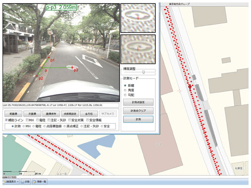
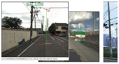
2. Reduced cost of measurement equipment and significantly improved measurement resolutionMany MMSs are equipped with a laser scanner, so they are considered complete surveying devices for measurement. An MMS equipped with a laser scanner for measuring the area around a road can easily extract information about objects having a clear shape. It has been used for automatically extracting information about utility poles, etc. Since the identification of road signs requires more than measuring their shape, cameras have also been used in conjunction with laser scanners. For measuring all features with a single device, we have been developing an MMS to measure shape with cameras. Many laser scanners (i.e., surveying devices) have been used to acquire a point cloud of tens of thousands of points per second while the measurement vehicle is moving. Laser scanners that measure with a measurement pulse of one million points per second have also been installed; however, laser scanners with higher densities are not being used because of their high equipment cost and long post-processing of data. Moreover, the measurement pulse of a laser scanner at a scan rate of one million points per second has a point-group interval of several centimeters that extends 5 m in the scanning-line direction, and when the measurement vehicle is traveling at 40 km/h, the point-group interval is about 10 cm. Therefore, it has not been possible to obtain sufficient data to determine the shape of small-diameter cables and colored features having high reflectivity. To enable 3D measurement only by shooting the subject with cameras, our MMS improves measurement accuracy by implementing a measurement technology using stereo cameras. Since the original data obtained with this technology has a high measurement resolution on the order of millimeters, it is possible to measure small-diameter cables (Fig. 3). When up to eight cameras are installed and operated, two stereo cameras are placed in the front and six cameras can be optimally configured according to the measurement target. Our MMS is currently equipped with cameras with resolutions of 20 to 30 million pixels (roughly equivalent to 8K). To improve the performance of our MMS, we have been verifying many types of cameras with various specifications every year and practically applied them as a system applicable to MMSs.
3. Reducing cost of measuring self-position of a vehicleThe equipment of an MMS for measuring the self-position of a vehicle mainly consists of a global navigation satellite system (GNSS), inertial measurement unit (IMU), and odometer. These devices generally increase the cost of configuring an MMS. Many satellite-positioning systems are equipped with one or more high-precision GPS (Global Positioning System) antennas, which contribute to their high cost. When the measurement method based on virtual reference points is used, satellite correction data are sent and received after the vehicle with an MMS starts running, so improving the efficiency of data post-processing is another issue. We adopted a high-sensitivity receiver that can be used when the vehicle is moving. It eliminates the need for calibration running before and after measurement and stopping operation for a certain period to maintain a fixed state (i.e., stabilization of satellite positioning) while the measurement is being conducted. As a result, the actual time that the measurement can be conducted over a day has been extended. While verifying devices that integrate GNSS receivers and IMU functions, devices that can receive GNSS positioning signals at two frequencies, and devices that can receive a correction signal from the quasi-zenith satellite system MICHIBIKI, we are currently striving to improve the accuracy of self-position measurement. Our other initiatives include verifying IMU devices (aiming to reduce prices) and testing the performance of different types of odometer systems. 4. Expanding application area to facility inspectionOur MMS manages 3D measurement data (latitude/longitude, altitude, and dimensions) and image information (cracks, corrosion, wear, etc.) by using a GIS (geographic information system) platform called Triple I+P (Infrastructure, IT, Innovation Platform) and can be used together with information about communication facilities. Since images that enable 3D measurement are acquired, it is easy to apply image-based artificial intelligence (AI) to those images, which makes it possible to significantly improve the efficiency of facility inspection. In the case of image AI, it is common to learn and identify images. However, by taking advantage of 3D measurement capability and adding the size of the object (in addition to image information) to the index for identifying objects, our MMS can determine the type of object in the image. In other words, inspection accuracy is improved by applying AI processing that adds the dimensions of the target object to the image diagnosis (Fig. 4).
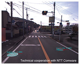
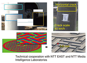
NTT EAST and NTT WEST are already operating our MMS for inspecting communication facilities such as utility poles. The practical application of our MMS has made it possible to use AI in areas containing features that are difficult to measure with a laser scanner, such as rust, stains, and cracks (Fig. 5).
5. Future developmentsOur MMS uses data obtained via an in-vehicle electronic platform, so its operation is not limited to a specific vehicle model. In the future, we plan to design, develop, and commercialize MMSs using small (lightweight) vehicles and an MMS using push carts for sidewalks and narrow roads along which vehicles cannot pass while making it possible to efficiently digitize geospatial information.
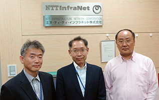
Authors (from left): Tomomi Matsuda, Manager, DX Promotion Headquarters, NTT InfraNet; Toshihiko Sekiguchi, Manager, DX Promotion Headquarters, NTT InfraNet; and Yasufumi Yamamoto, Assistant Manager, DX Promotion Headquarters, NTT InfraNet |
||