|
|||||||||||||||||||||||||||||||
|
|
|||||||||||||||||||||||||||||||
       |
Regular Articles Vol. 13, No. 10, pp. 50–57, Oct. 2015. https://doi.org/10.53829/ntr201510ra2 Development of World’s Highest Density Ultra-high-count and High-density Optical Fiber Cable (2000 Cores)AbstractWith the diversification of network services, we can expect an increase in optical demand. To provide these services in a timely manner, we must utilize the limited number of available underground facilities both economically and effectively. We have developed the world’s highest density ultra-high-count and high-density cables (2000 cores), an underground closure, and a water sensor module, which contribute to the effective use of underground facilities. Keywords: optical fiber cable, rollable fiber ribbon, multiple cable installation
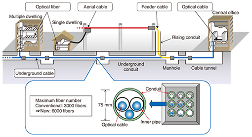
1. IntroductionCurrently, more than 26 million fiber-to-the-home (FTTH) subscribers (48% of Japanese households) enjoy broadband services via optical fiber, which has now reached the mature stage. However, we expect a further increase in the demand for FTTH services because the Japanese government is promoting the ICT Growth Strategy, which includes creating new scenarios for information and communication technology (ICT) use, solving social problems, and improving and strengthening the common ICT infrastructure. This raises concerns about the shortage of conduits in underground facilities that will result from the increased installation of underground optical cables. Consequently, we must utilize the limited number of available underground facilities both economically and effectively. If we are to construct economical and efficient access networks, we need high-count and high-density cables that can make the best use of existing underground facilities. To meet this requirement, we developed the world’s highest density ultra-high-count and high-density optical fiber cable (2000 cores) that employs a novel optical fiber ribbon. We describe the cable and related components consisting of an underground closure and a water sensor module in the following sections. 2. New development conceptConventionally, three 1000-core underground optical cables can be accommodated in a conduit by using a multiple cable installation technique, and thus, a maximum of 3000 fibers can be installed in one conduit [1]. If we are to use the multiple cable installation technique effectively, we need to design a new optical cable that has the same diameter as the current 1000-core optical cable (23 mm). The technique that is currently used for installing multiple cables in conduits is shown in Fig. 1. We have developed a new technique that enables us to install three 2000-core underground optical cables in a conduit, which means that a maximum of 6000 fibers can be accommodated per conduit. This technique makes it possible to reduce the cost of constructing underground facilities.
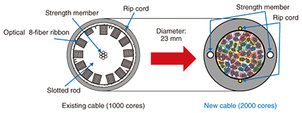
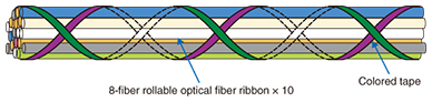
3. Ultra-high-count and high-density optical fiber cable (2000 cores)3.1 Optical fiber cable structureThe configurations of the existing cable and the new ultra-high-count and high-density optical fiber cable (2000 cores) are shown in Fig. 2. The new cable is composed of 250 rollable fiber ribbons (each with 8 fibers), as well as strength members, rip cords, and a polyethylene sheath. The 250 ribbons are grouped into 25 units. Each unit contains 10 of the 8-fiber rollable fiber ribbons that are formed into strands. Two pieces of colored tape are crossed over each other and wound around each unit to enable them to be identified, and the intersections are glued together to improve the handling of each unit (described in more detail in the following subsections). The incorporated optical fiber is commercially available fiber specified in the ITU-T (Telecommunication Standardization Sector of the International Telecommunication Union) G.657.A1 standard. We succeeded in developing 2000-core optical fiber cable with an outer diameter of 23 mm by using these techniques and optimizing the cable structure, which included designing the appropriate thickness of the polyethylene sheath that protects the fibers.
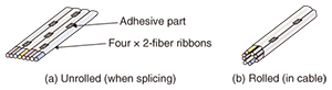
3.2 Optical fiber ribbon structureWe use a ribbon that we call rollable fiber ribbon for this cable. The configuration of this novel fiber ribbon is shown unrolled in Fig. 3(a). The ribbon is composed of four conventional optical 2-fiber ribbons that are arranged linearly, achieving a total of eight fibers. Each 2-fiber ribbon is composed of two coated optical fibers 250 μm in diameter. Two neighboring 2-fiber ribbons are fixed together periodically in the longitudinal direction. This structure enables the optical fiber ribbon to be rolled up easily, as shown in Fig. 3(b), and accommodated very tightly in the cables. Mass splicing can be used to splice the fibers just as with conventional fiber ribbon.
3.3 New method of identifying and selecting the needed optical fiberWith this cable, we needed to consider a new method of identifying and selecting the type of optical fiber needed due to the change in the structure of the accommodated fibers. Conventionally, when we identify and select the optical fiber, we first use a slotted rod to identify the unit. Then, we choose the needed optical fiber based on the color combination of each fiber. Our newly developed cable does not have a slotted rod inside; therefore, we use two pieces of colored tape that cross over each other and wind around each unit to identify which type of optical fiber the unit contains (Fig. 4). Two lengths of colored tape are chosen from a selection of 10 different tape colors that are used for identifying current aerial cable units. In the new cable, we use a combination of two tape colors to identify the unit number, and then we choose the optical fiber that is needed just as with the existing cable. This new method of identifying and selecting the needed optical fiber facilitated our development of the ultra-high-count and high-density optical fiber cable (2000 cores).
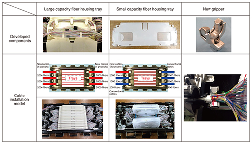
4. Underground closureWe also developed the components needed to construct an underground closure for use as the connection points for the new cable. To minimize the development cost, we adopted the conventional closure chassis [2]. 4.1 Large capacity fiber housing trayThis large capacity tray is specifically used when connecting new cables to each other. It can house 400 fibers, and we can install 15 trays in a conventional closure chassis. Therefore, we have successfully developed a closure that can house 3 new cables, or 6000 fibers (Fig. 5).
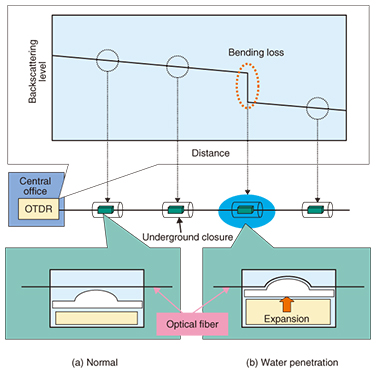
4.2 Small capacity fiber housing trayThis tray is specifically used for connecting new cable and conventional low-count optical fiber cable when wiring certain existing routes. It can house 80 fibers. This number is twice that of the conventional tray with the same workability because we consider the workspace and optimize the number of trays that can be used in this closure. We can install 40 trays in a conventional closure chassis, so 3200 fibers can be housed in conventional closures (Fig. 5). 4.3 New gripper for strength memberA gripper is used to hold on to the strength member in order to limit the movement of the strength member. We improved the gripping of the strength member for the developed closure for the following reasons: (1) Conventional cables have a slotted rod and a strength member in the center of the cable (Fig. 2). The conventional gripper used for the strength member inside the closures is the optimized configuration for cables having a slotted rod. (2) The new cable configuration does not have a slotted rod, and it has two strength members outside the bundle of fibers (Fig. 2). Moreover, the diameter of the strength member and the sheath thickness of the new cable are larger than the conventional values. Therefore, the conventional gripper is unsatisfactory for handling the new cable. We decided that the new cable needed a new gripper, and we determined the requirements for the new gripper by conducting an experimental investigation. 4.3.1 Experimental discussionWe conducted a heat cycle experiment to investigate the case in which the strength member is pulled or pushed from the cable sheath. In the experiment, the phenomenon in which the strength member is pulled and pushed from the cable by a heat cycle did not occur. Therefore, the new gripper must meet the following requirements. First, there must be no gripping force needed for the strength member. Also, the strength member needs to have conductivity. 4.3.2 Development of new gripperWe developed a new gripper based on the above result. We discuss here three important requirements: (1) conductivity must be achieved when the strength member and the gripper are in contact; (2) the new gripper must enable new cable to be installed regardless of the orientation of the installed cable; and (3) the gripper must not have an adverse effect on the fibers in the new cable. The new gripper is shown in Fig. 5. It consists of a continuity base and a continuity clasp. We adopted a gripping technique that uses a spring, and we attached the spring to the insertion opening of the strength member, which meets requirement (1). We also adopted a configuration that allowed us to rotate the clasp. Therefore, the cable installation is independent of the strength member installation, and we meet requirement (2). In regard to requirement (3), the configuration of the continuity clasp is semicircular, and the edge of the clasp is chamfered. Thus, the clasp has little effect on the fibers in a new cable when the new cable is installed in a closure. 5. Water sensor moduleWater penetrating an underground closure over time can increase optical loss and degrade mechanical strength. For this reason, water sensor modules are attached to optical fibers for maintenance use in each underground closure. The water sensor module and the detection mechanism are shown in Fig. 6. If water penetrates the underground closure, the material encasing the water sensor module expands and applies a bending loss to the optical fiber. Water penetration in each underground closure can therefore be monitored by performing a periodic optical time domain reflectometer (OTDR) test [3, 4].
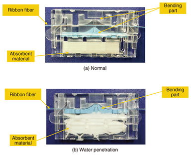
The proposed water sensor module is shown in Fig. 7. We applied the rollable fiber ribbon using bend-insensitive fibers to the optical fiber for maintenance use in the ultra-high-count and high-density optical fiber cable. We optimized the shape of the bending part of the water sensor module in order to apply a bending loss to the rollable fiber ribbon.
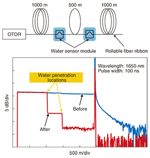
The experimental setup and the measured OTDR traces are shown in Fig. 8. The wavelength of the test light was 1650 nm, and the pulse width was 100 ns. From these OTDR traces, we were able to detect both water penetration locations.
6. ConclusionWe have developed an ultra-high-count and high-density (2000-core) optical fiber cable as well as an underground closure and water sensor module. These components make it possible to increase the maximum fiber count in a conduit and make effective use of underground facilities. They will contribute to further large-scale deployment of FTTH services. References
|
||||||||||||||||||||||||||||||